
How to efficiently test modifications or refine a mesh without going back to the CAD and mesher step?
Industrial context: Why mesh-level interface handling is a key feature for model design optimization in vibration related challenges?
In design processes, entering simulation phase comes along with optimization. To achieve an optimal cost/performance ratio, many design variations must be tested, based on CAD revisions, material choices, etc…
Vibration related challenges often come during refinement phases, once a design baseline has been stabilized. This is a natural sequence of events often induced by the fact that design offices have limited access to realistic environment integration parameters and advanced simulation tools. NVH considerations thus arise during experimental prototyping.
Fine tuning vibration/damping optimization can be sensitive, best performed with a high number of design point evaluations. This enables parametric mode tracking or mode shape classification. As the baseline design parameters remain mostly constant, design modifications at the mesh level are critical for performance. This is why we develop local remeshing and morphing tools in SDT, enabling us to refine local connections, alter local topologies, or add dissipation devices such as viscoelastic patches.

Materializing new interfaces in a mesh is thus a key functionality whose features should include
- Local refinement strategy with mesh compatibility
- Insertion of physical lines or surfaces in a mesh
- Mesh dissociation along a given interface
These features are given here as a default sequence considering that the initial mesh was not prepared to consider an interface at the location of interest. Of course, any clever preliminary work at the CAD and/or initial meshing level could ease these steps!
I/ How to fine tune existing interface? Local refinement.
Interfaces, or detail additions in a mesh often require local refinement to integrate a smaller scale without generating too heavy models. SDT features several refinement strategies depending on the need. The most straightforward implementations are in feutil refine and feutil divide commands. These commands perform elementwise refinements and work best on structured meshes. For local refinements interface continuity is not always guaranteed but MPC-based interface connections are available.
To perform local refinement with mesh compatibility fe_shapeoptim refine commands implement groupwise strategies to ensure a compatible transition between the refined area and the base one.
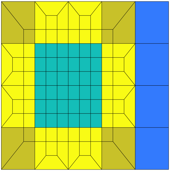
Local hierarchical refinement in a sample plate, and an engine cradle shell mesh with local triangle inclusions.
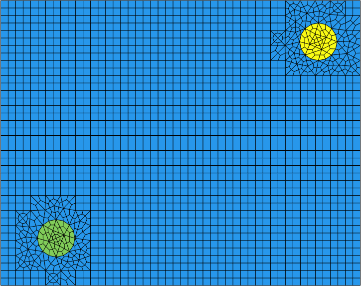
This kind of refinement requires working on quadrangles for surfaces. Triangle inclusion for quadrangle dominant meshes are also handled. Mesh transformations can however be necessary when triangles or tetrahedra are dominant. 3:1 quadrangle refinement from triangles and the volume equivalent can be performed to recover quadrangles and hexahedra.
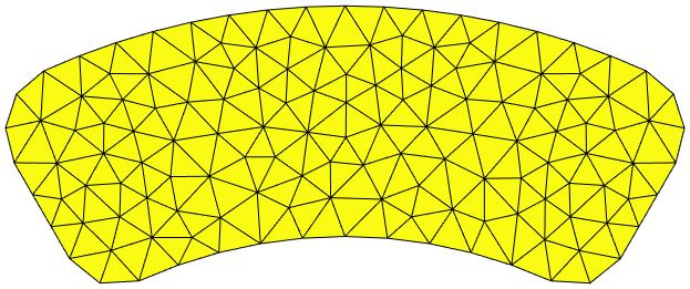
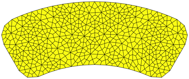
Triangle mesh conversion to quadrangle mesh, example of an automotive brake pad surface.
The advantage of hierarchical refinement is that the original topology is still underlaying. In particular all original nodes are still present at the same position. Observation and tracking can then be uniformly defined on all meshes for global response. In addition, for more advanced use, multi-scale coupling gets easier with an exact coarse mesh inclusion at all levels.
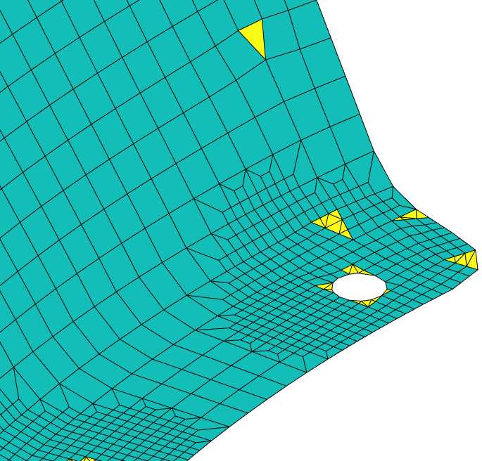
II/ How to efficiently introduce new interfaces? Insertion of physical lines at the mesh level.
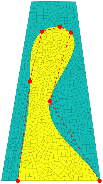
With a mesh of reasonable characteristic length, insertion of physical lines can be considered. We call physical line a contour line defined independently from the mesh. It can be an analytical shape, or a discretized line shape. It can, for example, refer to holes or material delimitations. For damping design, it can also allow described geometry of a viscoelastic patch to be added, as for the illustration below – based on a rotor blade damping study demonstration. Insertion of piezoactuators/sensors is another useful case!
If the original mesh does not integrate the physical line, a so-called mesh cut operation must be performed. These commands are implemented in SDT and OpenFEM in the lsutil cut commands. They exploit the level-set concepts to project the added internal shape on the existing mesh. From this projection, the interface line is integrated by local mesh modifications along it: either node displacement or edge splits, depending on the position tolerances.
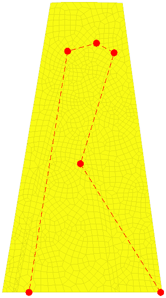
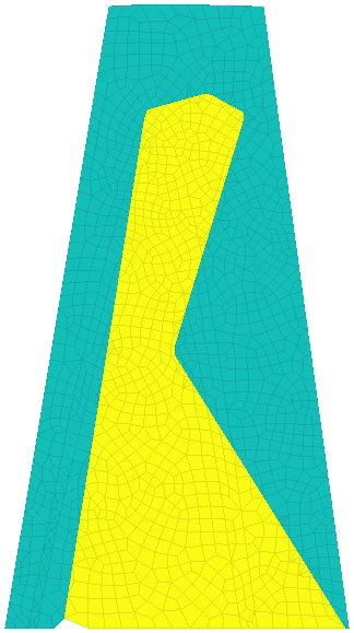
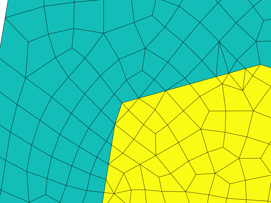
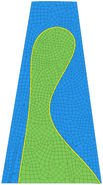
Physical line integration by mesh cut on a demonstration rotor blade skin
From the initial red points, a contour line is defined, and a distance-based level set is generated for projection. During the cut a different material identifier is given to differentiate the areas. In the zoomed-in areas, local remeshing induced by the line integration is visible.
In some specific context, including topology optimization needs, control points can be defined to parametrize the line, along with an interpolation strategy. Spline interpolation is implemented in lsutil for such purpose.
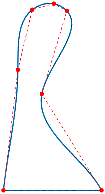
Physical line defined with spline interpolation integration by mesh cut on a demonstration rotor blade skin
Piezo patches insertion in a composite plate
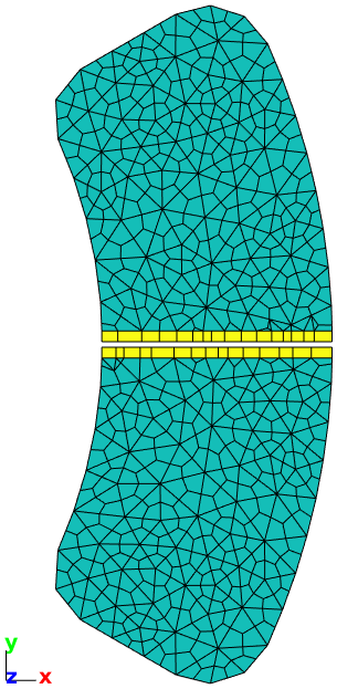
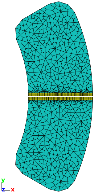
III/ How to model interface behavior? Mesh dissociation and interface layer.
So far, local refinement and physical line insertion have generated a controlled internal topology to an existing mesh. Using a specific interface behavior requires splitting the mesh to have an open interface where relative displacements can happen. This is also a requirement for some substructuring methods where components must be physically disjointed.
This operation is based on duplicating nodes at the interface and using old and new nodes in respective interface side. This functionality is implemented in SDT and OpenFEM in feutil unjoin. Its implementation allows customizing the model output with the new topology. Classical treatments all available in SDT include
- Implementation of zero thickness elements
- Implementation of a coupling superelement
- Definition of a contact pair
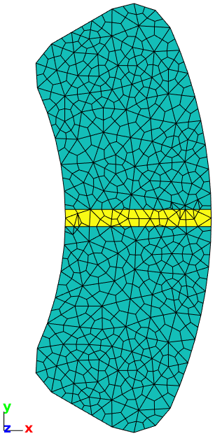
- Insertion of a transition layer
For the latter case, the mesh is further modified with morphing techniques to insert the layer along the line. No internal node is added inside, and quadrangles are generated to leave implementation flexibility and easy customization.

Mesh splitting along an interface with layer insertion
Example with pad slot on surface
Above fastener refinement and patch integration, another application of interest at SDTools is pad shape modification in the context of brake squeal mitigation. The tools presented in this post allow this kind of mesh modification as presented below. From the pad surface mesh presented earlier, a pad slot can be inserted, by
- meshing two physical lines delimitating the slot,
- unjoining the mesh with a transition layer,
- and removing the remaining insides.
- Local refinement can also be performed to refine the mesh around the slot.
Automotive brake pad slot insertion in surface mesh.