
Flange support around fasteners is a commonly overlooked topic in industrial structural dynamics applications. It is due to implementation complexity and the difficulty of finding relevant values for input parameters. It is however a very sensitive aspect that can prevent from validating a model when ignored.
We frequently need to add these features treating our clients’ case studies.
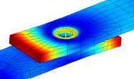
Implementation of flange support does not need to be complicated. Zero thickness elements are a practical way of modelling surface bounding features. They are implemented in SDT as flat bricks (hexa) or wedges (penta) elements and use 2D anisotropic shell constitutive properties.
This topology is a good basis to model glue or debonding, and to implement practical contact effects in dynamics.
As the pre-loaded contact conditions vary, the relevant constitutive parameters are generally unknown from design. Robust design and digital twin building must therefore assess their variability and provide critical configurations. In other approaches, model updating from test correlation will also be likely to highlight operational values for the model.
Having a distributed contact stiffness density is thus meaningful in many vibrations use cases:
👉 When flanges into contact have stiffness differences of several orders so that asperities compression and associated mean surface interpenetration must be accounted for. This is the case when liners or seals are present, or with coarse roughness.
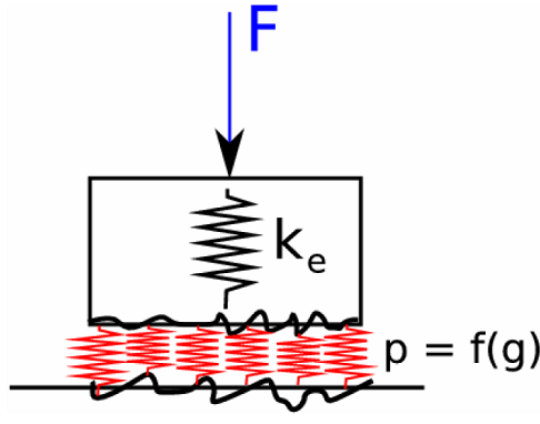
👉 When the contacting surface is not clearly defined so that the apparent stiffness accounts for unloaded areas. That is the case for fasteners, and is thus critical for assembled housing behavior and for vibration transmission to various equipment (PCB, battery packs…)
👉 When the dynamic response induces local contact surface changes so that an equivalent stiffness can be defined for a linear equivalent model.
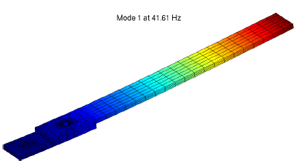
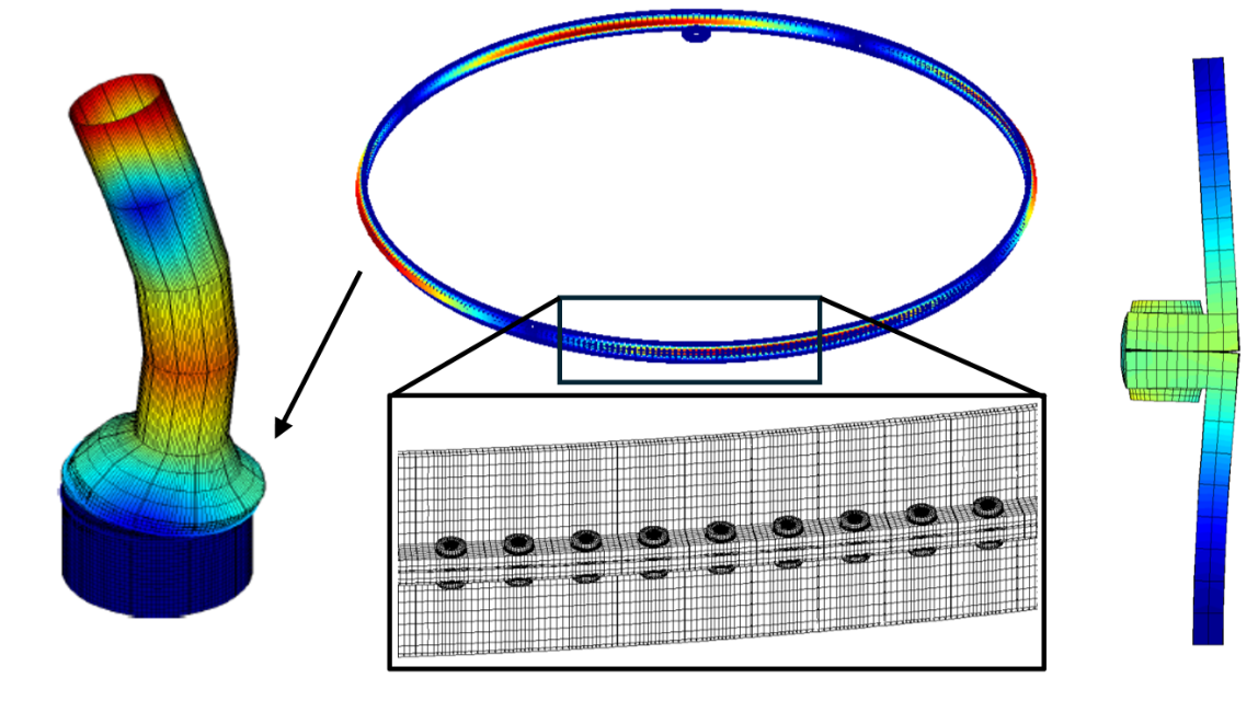
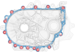
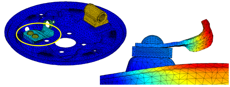
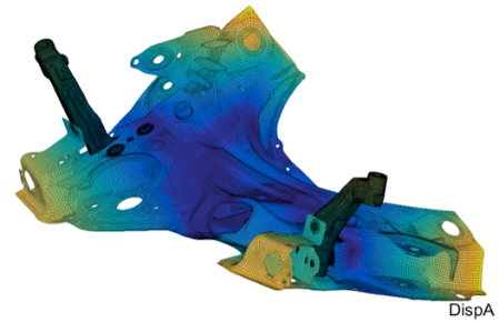
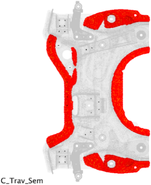
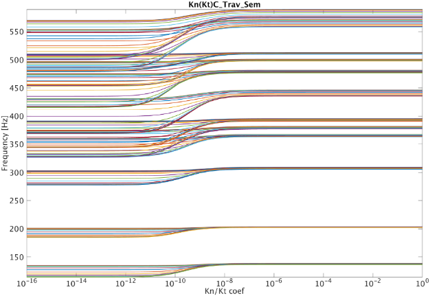
Varying equivalent elastic contact properties is thus essential for model validation [4]. The example below based on [2] illustrates how the natural frequencies of an engine cradle vary when considering a support stiffness on potential contacting areas around weld spots. The variation is over 10 % and must be considered as a first order parameter.
The challenge resides in the need for the defined contact parameters to remain easily accessible and portable to other codes. Solutions based on contact, surface constraint definition or direct matrix coupling have many drawbacks. When letting the code interpret contact or surface constraints, matching is required, and each code use frequently undocumented smoothing/weighting tweaks for convergence. In many cases, implementation variation in complex models significantly alters the expected result after export, and elastic behavior is seldom available. Exporting constraint matrices is impractical, generates heavy files, and is mesh dependent, making it an undesirable solution despite providing equivalent results.
Zero thickness elements match the requirements. They use classical topologies making it easy to recover stiffness matrix contributions and to parameterize.
Exports to other codes can be based on cohesive elements. These elements are widely available and suitable to our needs. We successfully implemented it for ABAQUS using COH3D8 and COH3D6 elements with COHESIVE SECTION and TRACTION type of ELASTIC. INTER-elements in ANSYS, CIFHEX and CIFPENT for Nastran, CHEXCZ and CPENTCZ in Simcenter Nastran should provide equivalent solutions for the need. It corresponds to a bilinear formulation with no (or very high) debonding thresholds, shear effects are available for tangential adherence.
SDT-Contact provides conversion functionalities to generate zero thickness implementations from contact formulations or constraint-based surface coupling. As we commonly import models from external codes or from existing industrial processes, these features are critical to provide an effortless integration.
The limitation of zero thickness elements resides in the need for a compatible mesh between surfaces. Such feature can be obtained in meshing software, or by splitting preliminary meshed solids (as our Unjoin functionality https://www.sdtools.com/help/feutil.html#UnJoin). When the mesh is not compatible, it is always possible to use the master surface for the zero thickness elements support and use Multiple Point Constraints (MPC) between the zero thickness and the slave surface. For target use cases, locking risks and implementation variations induced by the MPC will be mitigated by the fact that a softer material is present.
References
![]()
[1] Understanding friction induced damping in bolted assemblies through explicit transient simulation.
G. Vermot des Roches, E. Balmes, ISMA 2014.
![]()
[2] Error localization and updating of junction properties for an engine cradle model.
G. Vermot des Roches, E. Balmes, S. Nacivet. ISMA 2016.
![]()
[3] Updating and design sensitivity processes applied to drum brake squeal analysis.
Martin, E. Balmes, G. Vermot des Roches, T. Chancelier. Eurobrake 2016.
![]()
[4] Numerical design and test on an assembled structure of a bolted joint with viscoelastic damping.
C. Hammami, E. Balmes, M. Guskov. MSSP 2015.