
An open source base library
The general purpose FEM environment of the SDT is now developed as part of the OpenFEM library, which provides elements (beam, shells, volumes, …), matrix and load assembly tools, stress computations. The open specification of data structures and element function services allows integration of user developments in the pre-/post-processors and solution methods. At the element level, SDT adds formulations piezoelectric volumes (all topologies), composite and piezo shells 4 node shells (based on an MITC4 formulation).
Solvers
The SDT provides optimized solutions for
- static response to loading cases,
- partial eigenvalue solutions,
- model reduction (Guyan,Craig-Bampton and MacNeal…) for Component Mode Synthesis or state-space model generation,
- creation of state-space models for easy incorporation in the Control Toolbox or SIMULINK®
- computation of frequency response functions.
SDT 6.0 introduces a GUI based handling of cases to handle complex definitions of loads, boundary conditions, constraints, physical parametrization, etc. Significant optimization for large scale computations, allows computation of models in the 500,000 DOFs range. Out-of-core capabilities, currently limited to post-processing, can deal with several million DOFs.
 | Model of a tympanic membrane with 34466 nodes, 103398 DOFs, and 21048 volume elements. On a Pentium III, assembly took 113 s and computation of 20 modes 289 s with the sparse factor requiring 243 MB. Courtesy Mattia Ferrazzini, Laboratory for Experimental Audiology, ENT Departement, University Hospital, Zuerich |
Visualization
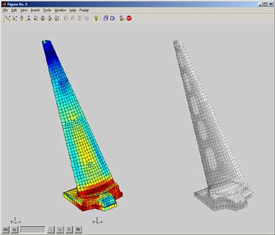
The object oriented GUI allows visualization and animation of FEM and test. You can combine 3-D surface, wire-frame, or sensor objects in the nominal or deformed configuration, redefine new deformations or sensor configurations for the current structure, scan through a set of deformations, efficiently zoom with the mouse, control amplification, animate real, complex, or color shapes, show selected substructures, rotate the structure, and more.
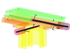 |
The various components of a model, here a milling platform, can be represented as superelement to allow predictions of the dynamic response in multiple configurations. |
Mesh manipulations
The femesh user interface enables the creation and extensive manipulations of finite element models. Commands allow element and node selection, translation, extrusion, repetition, revolution, mesh refinement… All these operations are compatible with both SDT and user defined elements and are used extensively for part visualization, parameterization, etc.
 |
SDT 6 introduces a complete revision of the FEM model property figure. This can now be used to view model properties, boundary conditions, … as well as launch computations from the solver tab. The feplot pointer object has also gone major revision for script/function based manipulations. |
Import/export
While femesh handles simple geometries, industrial models need general 3-D meshers that are only available in full fledged CAD systems. SDT FEMLINK thus provides interfaces with popular formats : NASTRAN, ANSYS, ABAQUS, Universal File Format, SAMCEF, PERMAS,…
Physical Parametrization
The upcom function allows easy manipulations of large parametrized models. Physical parameter variations (modulus, density, thickness…) can be associated with arbitrary element set selections. Model matrices, modeshapes,modeshape sensitivities,and frequency responses can be easily computed at each design point. The main applications of this interface are optimization and finite element model updating based on experimental data.