
 PDF Index
|
Contents
Functions
PDF Index |
Purpose
Finite element mesh handling utilities.
Syntax
[out,out1] = feutil('CommandString',model,...)
Description
feutil provides a number of tools for mesh creation and manipulation.
Some commands return the model structure whereas some others return only the element matrix. To mesh a complex structure one can mesh each subpart in a different model structure (mdl0, mdl1, ...) and combine each part using AddTest command. To handle complex model combination (not only meshes but whole models with materials, bases, ...), one can use the feutilb CombineModel command.
Available feutil commands are
Avanced command with non trivial input/output formats or detailed options are listed under feutila.
model.Elt=feutil('AddElt',model.Elt,'EltName',data)
This command can be used to add new elements to a model. EltName gives the element name used to fill the header. data describes elements to add (one row per element). Following example adds celas elements to the basis of a simple cube model.
femesh('Reset'); model=femesh('Testhexa8'); % simple cube model
data=[1 0 123 0 0 1 1e3; 2 0 123 0 0 1 1e3;
      3 0 123 0 0 1 1e3; 4 0 123 0 0 1 1e3]; % n1 n2 dof1 dof2 EltId ProId k
model.Elt=feutil('AddElt',model.Elt,'celas',data);
cf=feplot(model);
[AllNode,ind]=feutil('AddNode',OldNode,NewNode);
Combine (without command option New) or append (with command option New) NewNode to OldNode. Without command option New, AddNode combines NewNode to OldNode: it finds nodes in NewNode that coincide with nodes in OldNode and appends other nodes to form AllNode. With command option New, AddNode simply appends NewNode to OldNode.
AllNode is the new node matrix with added nodes. ind (optional) gives the indices of the NewNode nodes in the AllNode matrix.
NewNode can be specified as a matrix with three columns giving xyz coordinates. The minimal distance below which two nodes are considered identical is given by sdtdef epsl (default 1e-6).
[AllNode,ind]=feutil('AddNode From 10000',OldNode,NewNode); gives node numbers starting at 10000 for nodes in NewNode that are not in OldNode.
SDT uses an optimized algorithm available in feutilb.
By default, nodes that repeated in NewNode are coalesced onto the same node (a single new node is added). If there is not need for that coalescence, you can get faster results with AddNode-nocoal.
ind=feutilb('AddNode -near epsl value',n1,n2); returns a sparse matrix with non zero values in a given colum indicating of n1 nodes that are within epsl of each n2 node (rows/columns correspond to n1/n2 node numbers).
id=feutilb('AddNode -nearest epsl value',n1,xyz); returns vector giving the nearest n1 NodeId to each xyz node the search area being limited to epsl. When specified with a 7 column n2, the result is sparse(n2(:,1),1,n1_index). For fine meshes the algorithm can use a lot of memory. If n2 is not too large it is then preferrable to use an AddNode command with a tolerance sufficient for a match [n3,ind]=feutil('AddNode epsl value',n1,n2);id=n3(ind,1).
model=feutil('AddSetNodeId',model,'name','FindNodeString') adds the selection FindNodeString as a set of nodes name to model. 'FindNodeString' can be replaced by a column vector of NodeId.
Syntax is the same for AddSetEltId with a FindEltString selection.
The option -id value can be added to the command to specify a set ID.
Following example defines a set of each type on the ubeam model:
model=demosdt('demo ubeam');
cf=feplot
model=feutil('AddSetNodeId',model,'nodeset','z==1');
model=feutil('AddSetEltId -id18',model,'eltset','WithNode{z==0}');
[elt,ind]=feutil('FindElt setname  eltset',model); % FindElt based on set name
r1=cf.Stack{'eltset'};r1.type='FaceId';r1.data(:,2)=1;
cf.Stack{'set','faceset'}=r1;
r1=cf.Stack{'nodeset'};r1.type='DOF';r1.data=r1.data+0.02;
cf.Stack{'set','dofset'}=r1;
fecom(cf,'curtab Stack','eltset');
model=feutil('AddTest',mdl1,mdl2);
Combine test and analysis models. When combining test and analysis models you typically want to overlay a detailed finite element mesh with a coarse wire-frame representation of the test configuration. These models coming from different origins you will want combine the two models in model.
If you aim at combining several finite element models into an assembly, with proper handling of materials, element IDs, bases,…, you should rather use the more appropriate feutilb CombineModel command.
The combined models can then be used to create the test/analysis correlation using fe_sens. An application is given in the gartte demo, where a procedure to match initially different test and FE coordinate frames is outlined. See sdtweb('pre') for details about test frame meshing strategies.
AddTest command attempts to retain as much information as possible (nodes, elements, materials, etc.) when adding the 2 models. This feature is however rather limited with complex models.
model=feutil('Divide div1 div2 div3',model);
Mesh refinement by division of elements.
Divide applies to all groups in model.Elt. To apply the division to a selection within the model use ObjectDivide. Currently supported divisions are
If your elements have a different name but the same topological structure declare the proper parent name or use the SetGroupName command before and after divide. The division preserves properties other than the node numbers.
You can obtain unequal divisions by declaring additional arguments whose lines give the relative positions of dividers. For example, an unequal 2 by 3 division of a quad4 element would be obtained using
model=feutil('divide',[0 .1 1],[0 .5 .75 1],model) (see also the gartfe demo).
% Example 1 : beam1
femesh('Reset'); model=femesh('Testbeam1');  % build simple beam model
model=feutil('Divide 3',model); % divide by 3
cf=feplot(model); fecom('TextNode'); % plot model and display NodeId

% Example 2 : you may create a command string
femesh('Reset'); model=femesh('Testbeam1');  % build simple beam model
number=3;
st=sprintf('Divide %f',number);
model=feutil(st,model);
cf=feplot(model); fecom('TextNode')

% Example 3 : you may use uneven division
femesh('Reset'); model=femesh('Testquad4');  % one quad4 created
model=feutil('Divide',model,[0 .1 .2 1],[0 .3 1]);
feplot(model);
An inconsistency in division for quad elements was fixed with version 1.105, you can obtain the consistent behavior (first division along element x) by adding the option -new anywhere in the divide command.
elt=feutil('DivideInGroups',model);
Finds groups that are not connected (no common node) and places each of these groups in a single element group.
elt=feutil('DivideGroup i ElementSelector',model);
Divides a single group i in two element groups. The first new element group is defined based on the element selectors (see section 7.12).
For example elt=feutil('divide group 1 withnode{x>10}',model);
[EltId]=feutil('EltId',elt) returns the element identifier for each element in elt. It currently does not fill EltId for elements which do not support it.
[EltId,elt]=feutil('EltIdFix',elt) returns an elt where the element identifiers have been made unique.
Command option -elt can be used to set new EltId.
model=femesh('TestHexa8')
[EltId,model.Elt]=feutil('EltIdFix',model.Elt); % Fix and get EltId
[model.Elt,EltIdPos]=feutil('eltid-elt',model,EltId*18); % Set new EltId
model.Elt(EltIdPos>0,EltIdPos(EltIdPos>0)) % New EltId
Extrusion. Nodes, lines or surfaces of model are extruded nRep times with global translations tx ty tz. Elements with a mass1 parent are extruded into beams, element with a beam1 parent are extruded into quad4 elements, quad4 are extruded into hexa8, and quadb are extruded into hexa20.
You can create irregular extrusions. For example, model=feutil('Extrude 0 0 0 1',model,[0 logspace(-1,1,5)]) will create an exponentially spaced mesh in the z direction. The second argument gives the positions of the sections for an axis such that tx ty tz is the unit vector.
% Example 1 : beam
femesh('Reset'); model=femesh('Testbeam1'); % one beam1 created
model=feutil('Extrude 2 1 0 0',model); % 2 extrusions in x direction
cf=feplot(model);

% Example 2 : you may create the command string
number=2;step=[1 0 0];
st=sprintf('Extrude %f %f %f %f',[number step]);
femesh('Reset'); model=femesh('Testbeam1'); % one beam1 created
model=feutil(st,model);
cf=feplot(model);

% Example 3 : you may uneven extrusions in z direction
femesh('Reset'); model=femesh('Testquad4');
model=feutil('Extrude 0 0 0 1',model,[0 .1 .2 .5 1]);
     % 0 0 0 1        :  1 extrusion in z direction
     % [0 .1 .2 .5 1] :  where extrusions are made
feplot(model)
Command to obtain DOF from a model, or from a list of NodeId and DOF.
Use mdof=feutil('GetDof',dof,NodeId); to generate a DOF vector from a list of DOF indices dof, a column vector (e.g. dof=[.01;.02;.03]), and a list of NodeId, a column vector. The result will be sorted by DOF, equivalent to mdof = [NodeId+dof(1);NodeId+dof(2);...].
Call mdof=feutil('GetDof',NodeId,dof); will output a DOF vector sorted by NodeId, equivalent to mdof = [NodeId(1)+dof;NodeId(2)+dof;...].
The nominal call to get DOFs used by a model is mdof=feutil('GetDOF',model). These calls are performed during assembly phases (fe_mk, fe_load, ...). This supports elements with variable DOF numbers defined through the element rows or the element property rows. To find DOFs of a part of the model, you should add a ElementSelector string to the GetDof command string.
Note that node numbers set to zero are ignored by feutil to allow elements with variable number of nodes.
Find elements based on a number of selectors described in section 7.12. The calling format is
[ind,elt] = feutil('FindElt ElementSelector',model);
where ind gives the row numbers of the elements in model.Elt (but not the header rows except for unique superelements which are only associated to a header row) and elt (optional) the associated element description matrix.
When operators are accepted, equality and inequality operators can be used. Thus group~=[3 7] or pro < 5 are acceptable commands. See also SelElt, RemoveElt and DivideGroup, the gartfe demo, fecom selections.
Find node numbers based on a number of node selectors listed in section 7.11.
Different selectors can be chained using the logical operations & (finds nodes that verify both conditions), | (finds nodes that verify one or both conditions). Condition combinations are always evaluated from left to right (parentheses are not accepted).
The calling format is
[NodeId,Node] = feutil('FindNode NodeSelector',model);
Output arguments are the NodeId of the selected nodes and the selected nodes Node as a second optional output argument.
As an example you can show node numbers on the right half of the z==0 plane using the commands
fecom('TextNode',feutil('FindNode z==0 & x>0',model))
Following example puts markers on selected nodes
demosdt('demo ubeam'); cf=feplot; % load U-Beam model
fecom('ShowNodeMark',feutil('FindNode z>1.25',cf.mdl),'color','r')
fecom('ShowNodeMark-noclear',feutil('FindNode x>0.2*z|x<-0.2*z',cf.mdl),...
      'color','g','marker','o')
Note that you can give numeric arguments to the command as additional feutil arguments. Thus the command above could also have been written feutil('FindNode z== & x>=',0,0))
See also the gartfe demo.
These feutil commands are used to create a mode containing the 1D edges or 2D faces of a model. A typical call is
 femesh('reset'); model=femesh('Testubeam');
 elt=feutil('GetEdgeLine',model); feutil('infoelt',elt)
GetEdgeLine supports the following variants MatId retains inter material edges, ProId retains inter property edges, Group retains inter group edges, all does not eliminate internal edges, InNode only retains edges whose node numbers are in a list given as an additional feutil argument.
These commands are used for SelEdge and SelFace element selection commands. Selface preserves the EltId and adds the FaceId after it to allow face set recovery.
Header row parsing. In an element description matrix, element groups are separated by header rows (see section 7.2) which for the current group jGroup is given by elt(EGroup(jGroup),:) (one can obtain EGroup - the positions of the headers in the element matrix - using [EGroup,nGroup]=getegroup(model.Elt)). The GetElemF command, whose proper calling format is
[ElemF,opt,ElemP] = feutil('GetElemF',elt(EGroup(jGroup),:),[jGroup])
returns the element/superelement name ElemF, element options opt and the parent element name ElemP. It is expected that opt(1) is the EGID (element group identifier) when defined.
Line=feutil('GetLine',node,elt) returns a matrix of lines where each row has the form [length(ind)+1 ind] plus trailing zeros, and ind gives node indices (if the argument node is not empty) or node numbers (if node is empty). elt can be an element description matrix or a connectivity line matrix (see feplot). Each row of the Line matrix corresponds to an element group or a line of a connectivity line matrix. For element description matrices, redundant lines are eliminated.
Patch=feutil('GetPatch',Node,Elt) returns a patch matrix where each row (except the first which serves as a header) has the form [n1 n2 n3 n4 EltN GroupN]. The ni give node indices (if the argument Node is not empty) or node numbers (if Node is empty). Elt must be an element description matrix. Internal patches (it is assumed that a patch declared more than once is internal) are eliminated.
The all option skips the internal edge/face elimination step. These commands are used in wire-frame and surface rendering.
Node=feutil('GetNode Selectors',model) returns a matrix containing nodes rather than NodeIds obtained with the feutil FindNode command. The indices of the nodes in model.Node can be returned as a 2nd optional output argument. This command is equivalent to the feutil call
[NodeId,Node]=feutil('FindNode Selectors',model).
[normal,cg]=feutil('GetNormal[elt,node]',model) returns normals to elements/nodes in model.
CG=feutil('GetCG',model) returns the CG locations. Command option -dir i can be used to specify a local orientation direction other than the normal (this is typically used for composites).
MAP=feutil('getNormal Map',model) returns a data structure with the following fields
| ID | column of identifier (as many as rows in the .normal field). For .opt=2 contains the NodeId. For .opt=1 contains the EltId. |
| normal | N× 3 where each row specifies a vector at ID or vertex. |
| opt | 1 for MAP at element center, 2 for map at nodes. |
| vertex | N× 3 matrix giving vertex positions if the map is not associated with nodes. |
The MAP data structure may be viewed using
fecom('ShowMap',MAP);fecom('ScaleOne');
feutil('Info',model); Information on model. Info by itself gives general information about model. InfoNodei gives information about all elements that are connected to node of NodeId i.
Join the groups i or all the groups of type EltName. JoinAll joins all the groups that have the same element name. Note that with the selection by group number, you can only join groups of the same type (with the same element name). JoinAll joins all groups with identical element names.
You may join groups using there ID
femesh('Reset'); model=femesh('Test2bay');
% Join using group ID
feutil('Info',model);   % 2 groups at this step
model=feutil('JoinGroup1:2',model)  % 1 group now
feutil('Info',model);
% Join using element types
% Note you can give model (above) or element matrix (below)
femesh('Reset'); model=femesh('Test2bay');
model.Elt=feutil('Joinbeam1',model.Elt);  % 1 group now
MatId=feutil('MatId',model) returns the element material identifier for each element in model.Elt.
One can also modify MatId of the model giving a third argument.
model=feutil('MatId',model,r1)
r1 can be a global shift on all non zero MatId or a matrix whose first column gives old MatId and second new MatId.
MatId renumbering is applyed to elements, model.pl and model.Stack 'mat' entries.
The ProId command works similarly.
MPId returns a matrix with three columns MatId, ProId and group numbers.
model.Elt=feutil('mpid',model,mpid) can be used to set properties of elements in model.Elt matrix.
elt=feutil('ObjectBeamLine i'); Create a group of beam1 elements. The node numbers i define a series of nodes that form a continuous beam (for discontinuities use 0), that is placed in elt as a single group of beam1 elements.
For example elt=feutil('ObjectBeamLine 1:3 0 4 5') creates a group of three beam1 elements between nodes 1 2, 2 3, and 4 5.
An alternate call is elt=feutil('ObjectBeamLine',ind) where ind is a vector containing the node numbers. You can also specify a element name other than beam1 and properties to be placed in columns 3 and more using elt=feutil('ObjectBeamLine -EltName',ind,prop).
elt=feutil('ObjectMass 1:3') creates a group of concentrated mass1 elements at the declared nodes.
model=struct('Node',[1 0 0 0  0  0 0;   2 0 0 0  0  0 .15; ...
                     3 0 0 0 .4  1 .176;4 0 0 0 .4 .9 .176], 'Elt',[]);
prop=[100 100 1.1 0 0]; % MatId ProId nx ny nz
model.Elt=feutil('ObjectBeamLine 1 2 0 2 3 0 3 4',prop);
% or model.Elt=feutil('ObjectBeamLine',1:4);
model.Elt=feutil('ObjectMass',model,3,[1.1 1.1 1.1]);
%model.Elt(end+1:end+size(elt,1),1:size(elt,2))=elt;
feplot(model);fecom textnode
model=feutil('ObjectHoleInPlate ...',model);
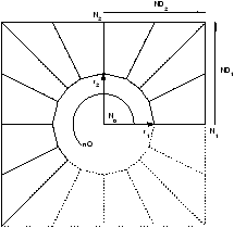 | Create a quad4 mesh of a hole in a plate. The format is 'ObjectHoleInPlate N0 N1 N2 r1 r2 ND1 ND2 NQ' giving the center node, two nodes to define the edge direction and distance, two radiuses in the direction of the two edge nodes (for elliptical holes), the number of divisions along a half quadrant of edge 1 and edge 2, the number of quadrants to fill (the figure shows 2.5 quadrants filled). |
model=struct('Node',[1 0 0 0  0 0 0; 2 0 0 0  1 0 0; 3 0 0 0  0 2 0],'Elt',[]);
model=feutil('ObjectHoleInPlate 1 2 3 .5 .5 3 4 4',model);
model=feutil('Divide 3 4',model); % 3 divisions around, 4 divisions along radii
feplot(model)
% You could also use the call
model=struct('Node',[1 0 0 0  0 0 0; 2 0 0 0  1 0 0; 3 0 0 0  0 2 0],'Elt',[]);
%   n1 n2 n3 r1 r2 nd1 nd2 nq
r1=[ 1  2  3 .5 .5  3   4   4];
st=sprintf('ObjectHoleInPlate %f %f %f %f %f %f %f %f',r1);
model=feutil(st,model);
model=feutil('ObjectHoleInBlock ...'); Create a hexa8 mesh of a hole in a rectangular block. The format is 'ObjectHoleInBlock x0 y0 z0 nx1 ny1 nz1 nx3 ny3 nz3 dim1 dim2 dim3 r nd1 nd2 nd3 ndr' giving the center of the block (x0 y0 z0), the directions along the first and third dimensions of the block (nx1 ny1 nz1 nx3 ny3 nz3, third dimension is along the hole), the 3 dimensions (dim1 dim2 dim3), the radius of the cylinder hole (r), the number of divisions of each dimension of the cube (nd1 nd2 nd3, the 2 first should be even) and the number of divisions along the radius (ndr).
mdl0=feutil('ObjectHoleInBlock 0 0 0 1 0 0 0 1 1 2 3 3 .7 8 8 3 2')
model=feutil('ObjectQuad MatId ProId',model,nodes,div1,div2) Create or add a model containing quad4 elements. The user must define a rectangular domain delimited by four nodes and the division in each direction (div1 and div2). The result is a regular mesh.
For example model=feutil('ObjectQuad 10 11',nodes,4,2) returns model with 4 and 2 divisions in each direction with a MatId 10 and a ProId 11.
An alternate call is model=feutil('ObjectQuad 1 1',model,nodes,4,2): the quadrangular mesh is added to the model.
node = [0  0  0; 2  0  0; 2  3  0; 0  3  0];
model=feutil('Objectquad 1 1',node,4,3); % creates model

node = [3  0  0; 5  0  0; 5  2  0; 3  2  0];
model=feutil('Objectquad 2 3',model,node,3,2); % matid=2, proid=3
feplot(model);
Divisions may be specified using a vector between [0,1] :
node = [0  0  0; 2  0  0; 2  3  0; 0  3  0];
model=feutil('Objectquad 1 1',node,[0 .2 .6 1],linspace(0,1,10));
feplot(model);
Other supported object topologies are beams and hexaedrons. For example
node = [0  0  0; 2  0  0;1  3  0; 1  3  1];
model=feutil('Objectbeam 3 10',node(1:2,:),4); % creates model
model=feutil('Objecthexa 4 11',model,node,3,2,5); % creates model
feutil('infoelt',model)
These object constructors follow the format
model=feutil('ObjectAnnulus x y z r1 r2 nx ny nz Nseg NsegR',model)
model=feutil('ObjectArc xc yc zc x1 y1 z1 x2 y2 z2 Nseg obt',model)
model=feutil('ObjectCircle x y z r nx ny nz Nseg',model)
model=feutil('ObjectCylinder x1 y1 z1 x2 y2 z2 r divT divZ',model)
model=feutil('ObjectDisk x y z r nx ny nz Nseg NsegR',model)
For example:
model=feutil('object arc 0 0 0 1 0 0 0 1 0 30 1');
model=feutil('object arc 0 0 0 1 0 0 0 1 0 30 1',model);
model=feutil('object circle 1 1 1 2 0 0 1 30',model);
model=feutil('object circle 1 1 3 2 0 0 1 30',model);
model=feutil('object cylinder 0 0 0  0 0 4 2 10 20',model);
model=feutil('object disk 0 0 0 3 0 0 1 10 3',model);
model=feutil('object annulus 0 0 0 2 3 0 0 1 10 3',model);
feplot(model)
Applies a Divide command to a selection within the model
node = [0  0  0; 2  0  0; 2  3  0; 0  3  0];
model=feutil('Objectquad 1 1',node,4,3); % creates model
model=feutil('ObjectDivide 3 2',model,'WithNode 1');
feplot(model);
model.Node=feutil('Optim...',model);
model.Node=feutil('OptimModel',model) removes nodes unused in model.Elt from model.Node.
model.Node=feutil('OptimNodeNum',model) does a permutation of nodes in model.Node such that the expected matrix bandwidth is smaller. This is only useful to export models, since here DOF renumbering is performed by fe_mk.
model=feutil('OptimEltCheck',model) attempts to fix geometry pathologies (warped elements) in quad4, hexa8 and penta6 elements.
Orient elements. For volumes and 2-D elements which have a defined orientation model.Elt=feutil('Orient',model) calls element functions with standard material properties to determine negative volume orientation and permute nodes if needed. This is in particular needed when generating models via Extrude or Divide operations which do not necessarily result in appropriate orientation (see integrules). When elements are too distorted, you may have a locally negative volume. A warning about warped volumes is then passed. You should then correct your mesh.
Note that for 2D meshes you need to use 2D element names (q4p, t3p, ...) rather than quad4, tria3, .... Typically model.Elt=feutil('setgroup1 name q4p',model).
Orient normal of shell elements. For plate/shell elements (elements with parents of type quad4, quadb or tria3) in groups i of model.Elt, model.Elt=feutil('Orient i n nx ny nz',model) command computes the local normal and checks whether it is directed towards the node located at nx ny nz. If not, the element nodes are permuted to that a proper orientation is achieved. A -neg option can be added at the end of the command to force orientation away rather than towards the nearest node.
model.Elt=feutil('Orient i',model,node) can also be used to specify a list of orientation nodes. For each element, the closest node in node is then used for the orientation. node can be a standard 7 column node matrix or just have 3 columns with global positions.
For example
% Init example
femesh('Reset'); model=femesh('Testquad4');
model=feutil('Divide 2 3',model);
model.Elt=feutil('Dividegroup1 WithNode1',model);
% Orient elements in group 2 away from [0 0 -1]
model.Elt=feutil('Orient 2 n 0 0 -1 -neg',model);
MAP=feutil('GetNormal MAP',model);MAP.normal
Basic element type transformations.
model=feutil('Lin2Quad epsl .01',model) is the generic command to generate second order meshes.
Lin2QuadCyl places the mid-nodes on cylindrical arcs.
Lin2QuadKnownNew can be used to get much faster results if it is known that none of the new mid-edge nodes is coincident with an existing node.
The inverse operation can be performed using Quad2Lin command.
Quad2Tria searches elements for quad4 element groups and replaces them with equivalent tria3 element groups.
Hexa2Tetra replaces each hexa8 element by four tetra4 elements (this is really not a smart thing to do).
Hexa2Penta replaces each hexa8 element by six tetra4 elements (warning : this transformation may lead to incompatibilities on the triangular faces).
Penta2Tetra replaces each penta6 element by 11 tetra4 elements.
Command option KnownNew can be used for Hexa2Tetra, Hexa2Penta, and Penta2Tetra. Since these commands add nodes to the structure, quicker results can be obtained if it is known that none of the new nodes are coincident with existing ones. In a more general manner, this command option is useful if the initial model features coincident but free surfaces (e.g. two solids non connected by topology, when using coupling matrices). The default behavior will add only one node for both surfaces thus coupling them, while the KnownNew alternative will add one for each.
% create 2x3 quad4
femesh('Reset'); model=femesh('Testquad4');
model=feutil('Divide 2 3',model);
model=feutil('Quad2Tria',model); % conversion
feplot(model)
% create a quad, transform to triangles, divide each triangle in 4
femesh('Reset'); model=femesh('Testquad4');
model=feutil('Quad2Tria',model);
model=feutil('Divide2',model);
cf=feplot(model); cf.model
% create a hexa8 and transform to hexa20
femesh('Reset'); model=femesh('Testhexa8');
model=feutil('Lin2Quad epsl .01',model);
feutil('InfoElt',model)
The RefineBeam command searches model.Elt for beam elements and divides elements so that no element is longer than l.
femesh('Reset'); model=femesh('Testbeam1'); % create a beam
model=feutil('RefineBeam 0.1',model);
The RefineToQuad command transforms first order triangles, quadrangles, penta, tetra, and hexa to quad and hexa only while dividing each element each in two. The result is a conform mesh.
mdl=femesh('testtetra4');mdl=feutil('RefineToQuad',mdl);
feplot(mdl);
[model.Elt,RemovedElt]=feutil('RemoveElt ElementSelectors',model);
Element removal. This function searches model.Elt for elements which verify certain properties selected by ElementSelectors and removes these elements from the model description matrix. 2nd output argument RemovedElt is optional and contains removed elements. A sample call would be
% create 3x2 quad4
femesh('Reset'); model=femesh('Testquad4');model=feutil('Divide 2 3',model);
[model.Elt,RemovedElt]=feutil('RemoveElt WithNode 1',model);
feplot(model)
Mat, Pro removal This function takes in argument the ID of a material or integration property and removes the corresponding entries in the model pl/il fields and in the stack mat/pro entries.
Sample calls are provided in the following to illustrate the use.
model=femesh('testhexa8');
model=stack_set(model,'pro','integ',p_solid('default'));
model=stack_set(model,'mat','steel',m_elastic('default steel'));
model=feutil('remove pro 110',model);
model=feutil('remove pro',model,111);
model=feutil('remove mat 100',model);
model=feutil('remove mat 100 pro 1',model);
model=feutil('remove pro -all',model); % Command option -all
model=feutil('remove mat pro -all',model);
model=femesh('testhexa8'); % Command option -unused
model=feutil('remove mat pro -unused',model);
model=feutil('Renumber',model,NewNodeNumbers) can be used to change the node numbers in the model. Currently nodes, elements, DOFs and deformations , nodeset, par, cyclic and other Case entries are renumbered.
NewNodeNumbers is the total new NodeIds vector. NewNodeNumbers can also be a scalar and then defines a global NodeId shifting. If NewNodeNumbers has two columns, first giving old NodeIds and second new NodeIds, a selective node renumbering is performed.
If NewNodeNumbers is not provided values 1:size(model.Node,1) are used. This command can be used to meet the OpenFEM requirement that node numbers be less than 2^31/100. Another application is to joint disjoint models with coincident nodes using
Command option -NoOri asks not to add the info,OrigNumbering data in the model stack. info,OrigNumbering is only useful when the user needs to convert something specific linked to the new node numerotation that is outside model.
[r1,i2]=feutil('AddNode',model.Node,model.Node);
model=feutil('Renumber',model,r1(i2,1));
Element group translation/duplication. RepeatSel repeats the elements of input model nITE times with global axis translations tx ty tz between each repetition of the group. If needed, new nodes are added to model.Node. An example is treated in the d_truss demo.
femesh('Reset'); model=femesh('Testquad4');
model=feutil('Divide 2 3',model);
model=feutil('RepeatSel 3 2 0 0',model); % 3 repetitions, tx=2
feplot(model)
% an alternate call would be
%                                            number, direction
% model=feutil(sprintf('Repeatsel %f %f %f %f', 3,  [2 0 0]))
Revolution. The elements of model are taken to be the first meridian. Other meridians are created by rotating around an axis passing trough the node of number OrigID (or the origin of the global coordinate system) and of direction [nx ny nz] (the default is the z axis [0 0 1]). nDiv+1 (for closed circle cases ang=360, the first and last are the same) meridians are distributed on a sector of angular width Ang (in degrees). Meridians are linked by elements in a fashion similar to extrusion. Elements with a mass1 parent are extruded into beams, element with a beam1 parent are extruded into quad4 elements, quad4 are extruded into hexa8, and quadb are extruded into hexa20.
The origin can also be specified by the x y z values preceded by an o using a command like model=feutil('Rev 10 o 1.0 0.0 0.0 360 1 0 0').
You can obtain an uneven distribution of angles using a second argument. For example model=feutil('Rev 0 101 40 0 0 1',model,[0 .25 .5 1]) will rotate around an axis passing by node 101 in direction z and place meridians at angles 0 10 20 and 40 degrees.
model=struct('Node',[1 0 0 0  .2 0   0; 2 0 0 0  .5 1 0; ...
                     3 0 0 0  .5 1.5 0; 4 0 0 0  .3 2 0],'Elt',[]);
model.Elt=feutil('ObjectBeamLine',1:4);
model=feutil('Divide 3',model);
model=feutil('Rev 40 o 0 0 0 360 0 1 0',model);
feplot(model)
fecom(';triax;view 3;showpatch')
% An alternate calling format would be
%      divi origin angle direct
% r1 = [40  0 0 0  360   0 1 0];
% model=feutil(sprintf('Rev %f o %f %f %f %f %f %f %f',r1))
Rotation. The nodes of model are rotated by the angle Ang (degrees) around an axis passing trough the node of number OrigID (or the origin of the global coordinate system) and of direction [nx ny nz] (the default is the z axis [0 0 1]). The origin can also be specified by the x y z values preceded by an o model=feutil('RotateNode o 2.0 2.0 2.0 90 1 0 0',model) One can define as a second argument a list of NodeId or a FindNode string comamnd to apply rotation on a selected set of nodes. model=feutil('RotateNode o 2.0 2.0 2.0 90 1 0 0',model,'x==1')
For example:
femesh('reset'); model=femesh('Testquad4'); model=feutil('Divide 2 3',model);
% center is node 1, angle 30, aound axis z
%                                     Center angle  dir
st=sprintf('RotateNode %f %f %f %f %f',[1      30   0 0 1]);
model=feutil(st,model);
feplot(model); fecom(';triax;textnode'); axis on
elt=feutil('SelElt ElementSelectors',model)
Element selection. SelElt extract selected element from model that verify certain conditions. Available element selection commands are described under the FindElt command and section 7.12.
Set properties of a group. For group(s) selected by number i, name name, or all you can modify the material property identifier j, the element property identifier k of all elements and/or the element group identifier e or name s. For example
 model.Elt=feutil('SetGroup1:3 Pro 4',model);
 model.Elt=feutil('SetGroup rigid Name celas',model)
If you know the column of a set of element rows that you want to modify, calls of the form model.Elt(feutil('FindEltSelectors',model),Column)= Value can also be used.
 femesh('Reset'); model=femesh('Testubeamplot');
 model.Elt(feutil('FindElt WithNode{x==-.5}',model),9)=2;
 cf=feplot(model);
 cf.sel={'groupall','colordatamat'};
Set an integration property data (ProId). You can modify an il property of ID i by giving its name and its value using an integrated call of the type
 model=femesh('testhexa8');model.il
 model=feutil('SetPro 111 Integ=2',model);model.il
The names related to the integration properties a documented in the p_functions, p_solid, p_shell, p_beam, ... To get a type use calls of the form p_pbeam('PropertyUnitTypeCell',1).
The command can also be used to define additional property information (.MAP for field at nodes, .gstate for field at integration points and .NLdata for non linear behavior data.
feutil('stringdof',sdof) returns a cell array with cells containing string descriptions of the DOFs in sdof.
Plane symmetry. SymSel replaces elements in FEel0 by elements symmetric with respect to a plane going through the node of number OrigID (node 0 is taken to be the origin of the global coordinate system) and normal to the vector [nx ny nz]. If needed, new nodes are added to FEnode. Related commands are TransSel, RotateSel and RepeatSel.
elt=feutil('Trace2Elt',ldraw);
Convert the ldraw trace line matrix (see ufread 82 for format details) to element matrix with beam1 elements. For example:
TEST.Node=[1001 0 0 0 0 0 0    ; 1003 0 0 0 0.2 0 0 ;
           1007 0 0 0 0.6 0 0  ; 1009 0 0 0 0.8 0 0 ;
           1015 0 0 0 0 0.2 0  ; 1016 0 0 0 0.2 0.2 0;
           1018 0 0 0 0.6 0.2 0; 1019 0 0 0 0.8 0.2 0];
L=[1001 1003 1007 1009];
ldraw(1,[1 82+[1:length(L)]])=[length(L) L];
L=[1015 1016 1018 1019];
ldraw(2,[1 82+[1:length(L)]])=[length(L) L];
L=[1015 1001 0 1016 1003 0 1018 1007 0 1019 1009 0];
ldraw(3,[1 82+[1:length(L)]])=[length(L) L];
TEST.Elt=feutil('Trace2Elt',ldraw);
cf=feplot(TEST)
Translation of the selected element groups. TransSel replaces elements by their translation of a vector [tx ty tz] (in global coordinates). If needed, new nodes are added. Related commands are SymSel, RotateSel and RepeatSel.
femesh('Reset'); model=femesh('Testquad4'); model=feutil('Divide 2 3',model);
model=feutil('TransSel 3 1 0',model); % Translation of [3 1 0]
feplot(model); fecom(';triax;textnode')
Please, note that this command is usefull to translate only part of a model. If the full model must be translated, use basiscommand gnode. An example is given below.
femesh('Reset'); model=femesh('Testquad4'); model=feutil('Divide 2 3',model);
model.Node=basis('gnode','tx=3;ty=1;tz=0;',model.Node);
feplot(model); fecom(';triax;textnode')
Duplicate nodes which are common to two groups. To allow the creation of interfaces with partial coupling of nodal degrees of freedom, UnJoin determines which nodes are common to the element groups Gp1 and Gp2 of model.Elt, duplicates them and changes the node numbers in Gp2 to correspond to the duplicate set of nodes. In the following call with 2 output arguments (2nd is optionnal), the columns of the matrix InterNode give the numbers of the interface nodes in each group [model,InterNode]=feutil('UnJoin 1 2',model).
 femesh('Reset'); model=femesh('Test2bay');
 feutil('FindNode group1 & group2',model) % nodes 3 4 are common
 model=feutil('UnJoin 1 2',model);
 feutil('FindNode group1 & group2',model) % no longer any common node
A more general call allows to separate nodes that are common to two sets of elements [model,InterNode]=feutil('UnJoin',model,'Selection1','Selection2'). Elements in Selection1 are left unchanged while nodes in Selection2 that are also in Selection1 are duplicated.
See also
feutila, fe_mk, fecom, feplot, section 4.2, demos gartfe, d_ubeam, beambar ...
