PDF Index
|
Contents
Functions
PDF Index |
Purpose
element function for scalar springs and penalized rigid links
Description
In an model description matrix a group of celas elements starts with a header row [Inf abs('celas') 0 ...] followed by element property rows following the format
[n1 n2 DofID1 DofID2 ProID EltID Kv Mv Cv Bv]
with
| n1,n2 | node numbers of the nodes connected. Grounded springs are obtained by setting n1 or n2 to 0. |
| DofID | Identification of selected DOFs. |
| For rigid links, the first node defines the rigid body motion of the other extremity slave node. Motion between the slave node and the second node is then penalized. DofID (positive) defines which DOFs of the slave node are connected by the constraint. Thus [1 2 123 0 0 0 1e14] will only impose the penalization of node translations 2 by motion of node 1, while [1 2 123456 0 0 0 1e14] will also penalize the difference in rotations.
| |
| For scalar springs, DofID1 (negative) defines which DOFs of
node 1 are connected to which of node 2. DofID2 can be used to specify different DOFs on the 2 nodes. For example [1 2 -123 231 0 0 1e14] connects DOFs 1.01 to 2.02, etc.
| |
| ProID | Optional property identification number (see format below) |
| Kv | Optional stiffness value used as a weighting associated with the constraint. If Kv is zero (or not given), the default value in the element property declaration is used. If this is still zero, Kv is set to 1e14. |
p_spring properties for celas elements take the form [ProID type KvDefault m c eta S]
Below is the example of a 2D beam on elastic supports.
model=femesh('Testbeam1 divide 10');
model=fe_case(model,'FixDof','2D',[.01;.02;.04]);
model.Elt(end+1,1:6)=[Inf abs('celas')]; % spring supports
model.Elt(end+[1:2],1:7)=[1 0 -13 0   0 0 1e5;2 0 -13 0   0 0 1e5];
def=fe_eig(model,[5 10 0]); feplot(model,def);
The element property row is defined by
[n1 n2 MatId ProId EltId x1 x2 x3 CID S OCID S1 S2 S3]
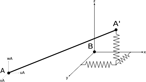
The orientation of the spring can be specified, by using distinct n1,n2, giving components x1,x2,x3 of an orientation vector (x1 should not be an integer if x2 and x3 are zero), a node number as NodeIdRef,0,0, the specification of a coordinate system CID.
The spring/damper is located at a position interpolated between n1 and n2 using S, such that xi = S n1 + (1−S) n2. The midpoint is used by default, that-is-to-say S is taken at 0.5 if left to zero. To use other locations, specify a non-zero OCID and an offset S1,S2,S3.
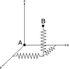
It is possible to set n2 to 0 to define a grounded cbush, or to define a local cbushusing n1=n2.
See also