2.3 Integrating thin piezocomposite transducers in plate models
2.3.1 Introduction
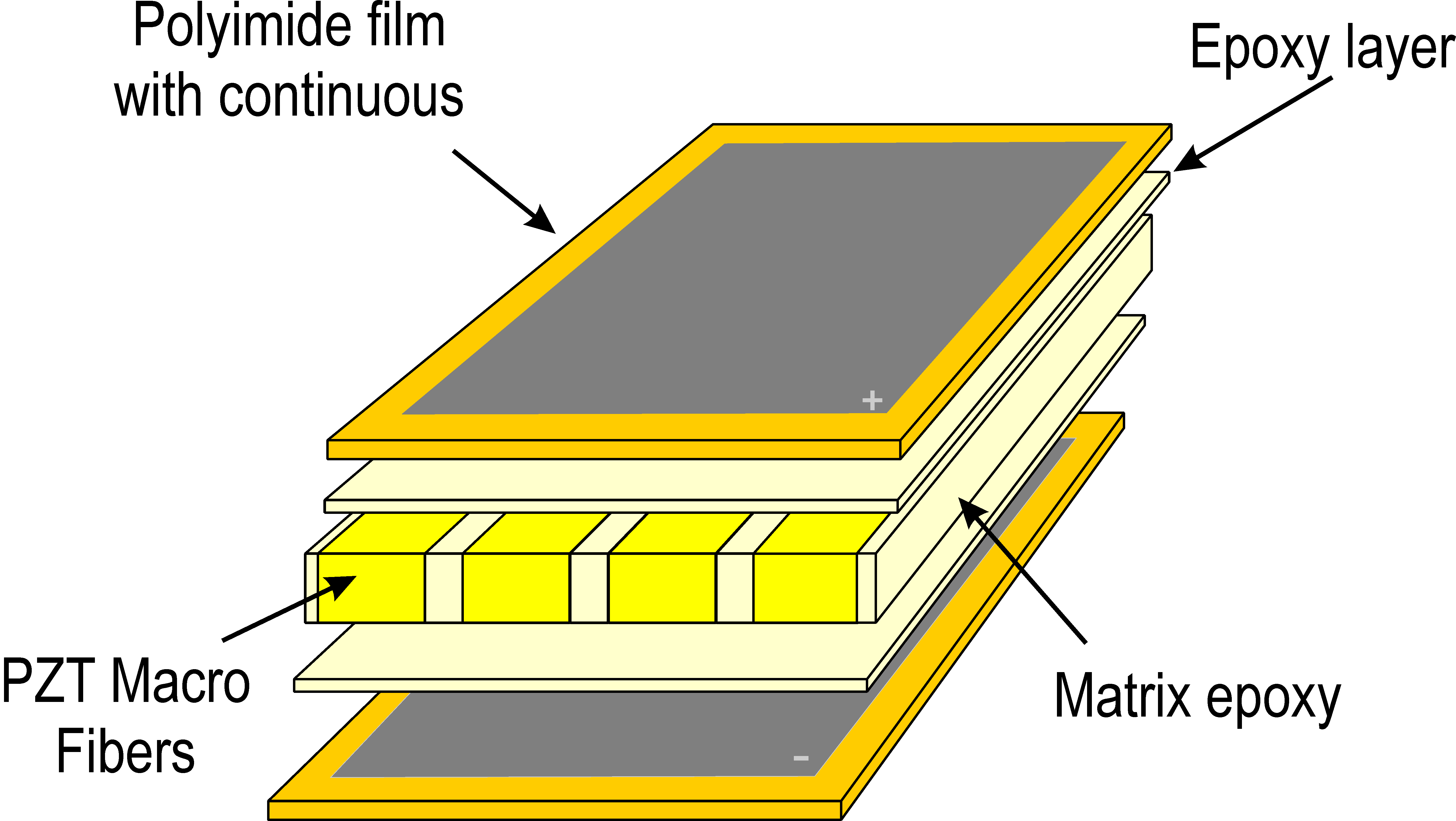
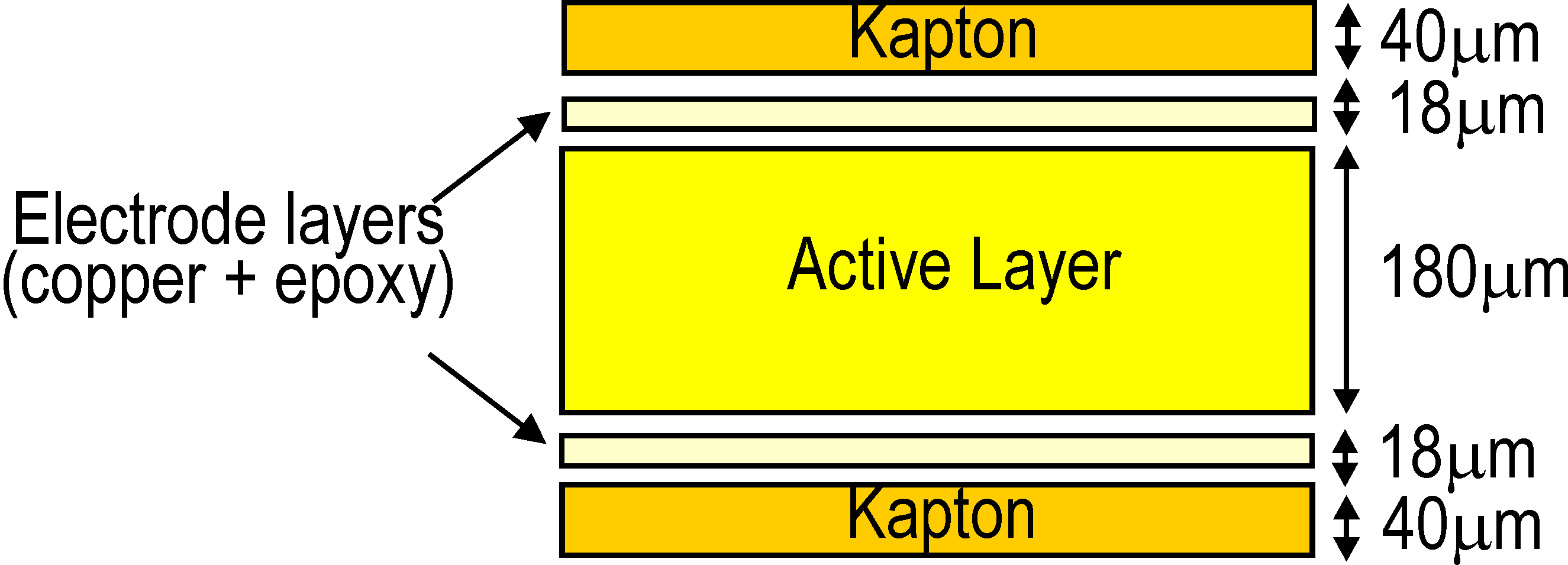
PZT ceramics are commonly used due to their good actuation capability and very wide bandwidth. The major drawbacks of these ceramics are their brittle nature, and the fact that they cannot be easily attached to curved structures. In order to overcome these drawbacks, several packaged PZT composites have appeared on the market. A typical piezocomposite transducer is made of an active layer sandwiched between two soft thin encapsulating layers (Figure 2.19).
| Figure 2.19: General layout of a piezoelectric composite transducer |
The packaging plays two different roles : (i) applying prestress to the active layer in order to avoid cracks, and (ii) bringing the electric field to the active layer through the use of a specific surface electrode pattern. Due to the difficulty to ensure contact between cylindrical fibers and the electrodes, rectangular fibers have been developed, leading to the 'Macro Fiber Composite' transducers initially developed by the NASA [] and currently manufactured by the company Smart Material (http://www.smart-material.com). As this type of transducer is widely used in the research community, this section shows how to integrate MFCs in piezoelectric plate models in SDT. Note however that all types of piezocomposites can be modeled, providing sufficient material data is available, which is rarely the case, as highlighted in the following for the case of MFCs.
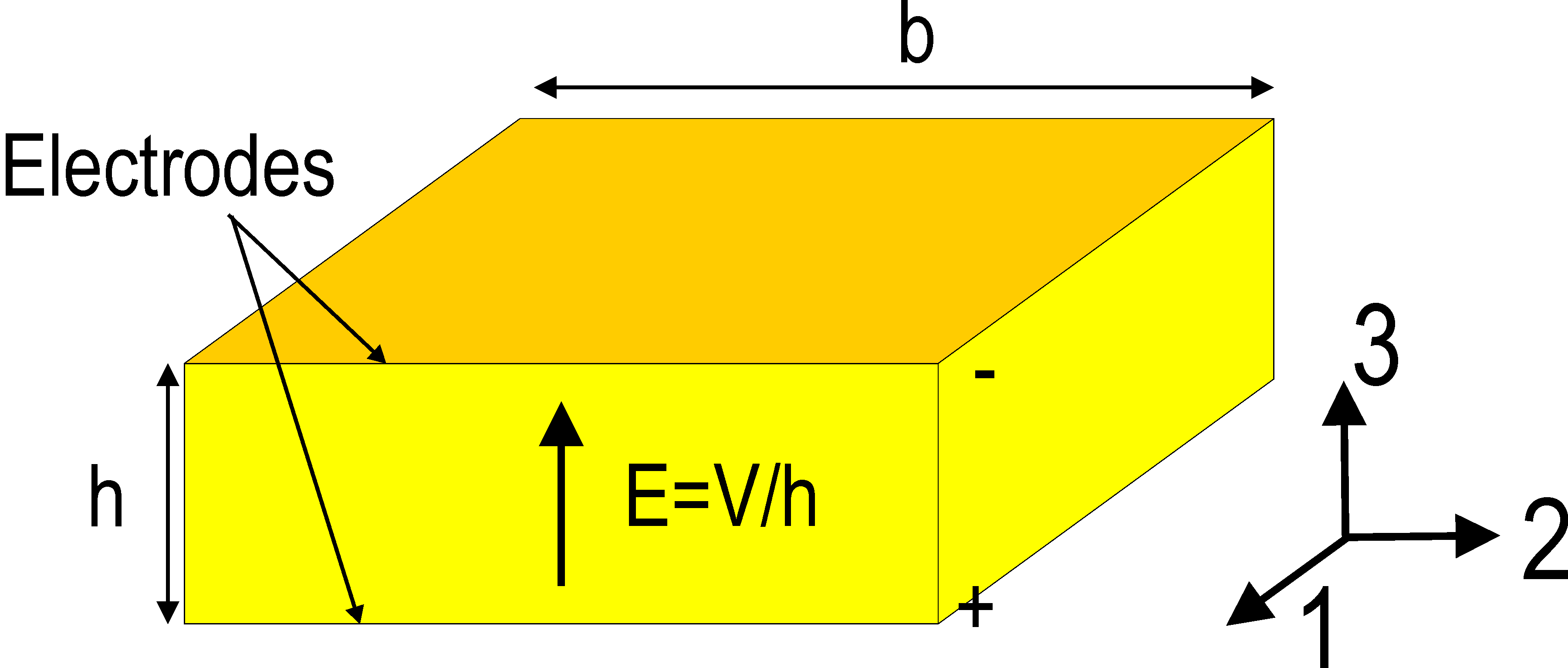
Both d31 and d33 MFCs have been developed. The d31 MFCs are based on the same concept as the bulk ceramic patches where poling is made through the thickness (Figure 2.20a).
a) b)
| Figure 2.20: Electric fields in a) d31 and b) d33 piezocomposites |
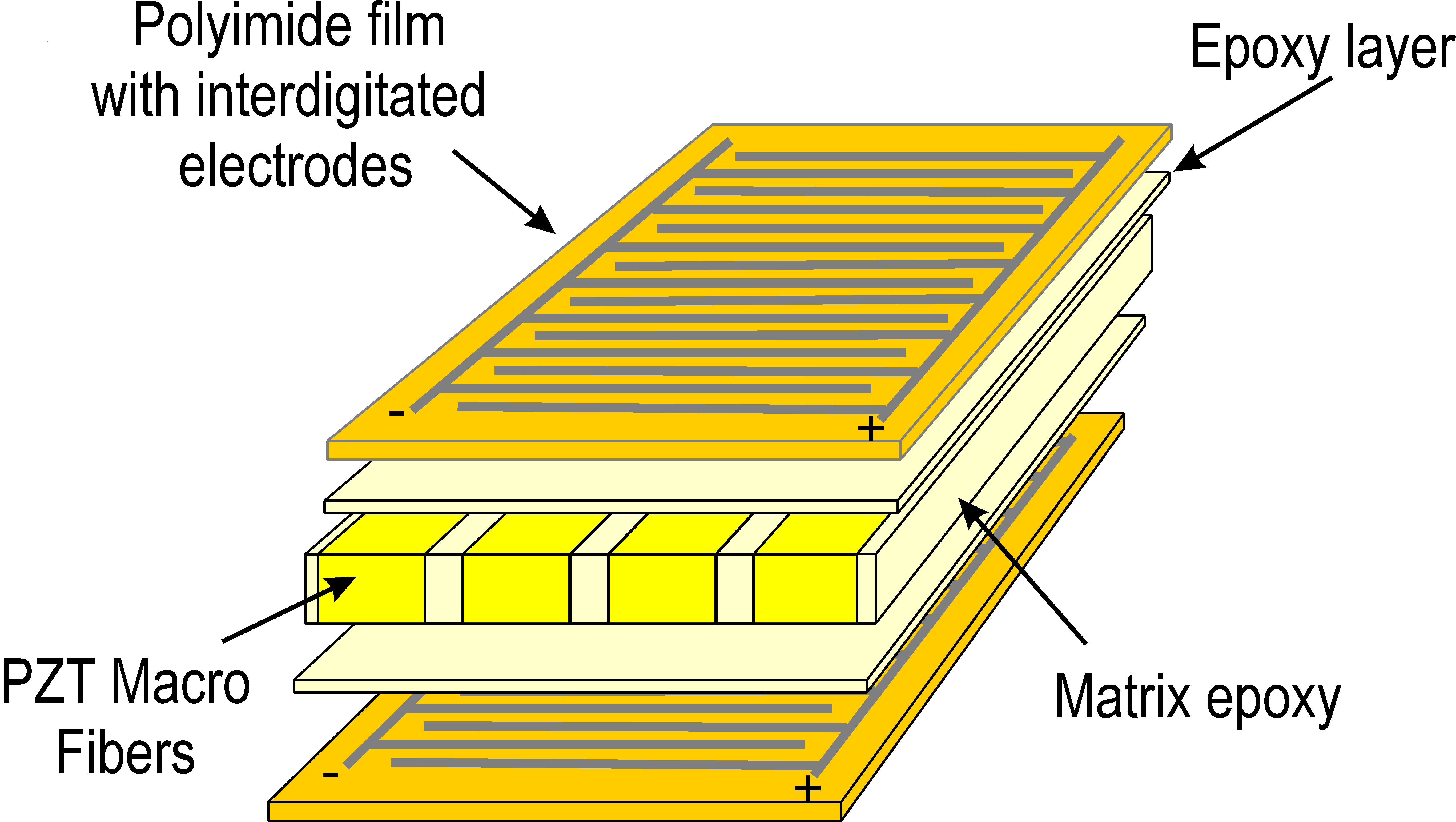
The d33 MFCs are aimed at exploiting the d33 actuation/sensing mode. This can be done by aligning the poling direction and the electric field with the fiber direction. The solution generally adopted is to use inter-digitated electrodes (IDE) as shown in Figure 2.20b, which results in curved electric field lines, with the majority of the electric field aligned in the fiber direction. The general layout of both types of MFCs is represented in Figure 2.21. In the Smart Material documentation, the d33-type is referred to as P1-type elongator (because d33>0) and the d31-type is referred to as P2-type contractor (because d31<0).
a) b)
| Figure 2.21: General layout of a) d31-type MFCs and b) d33-type MFCs |
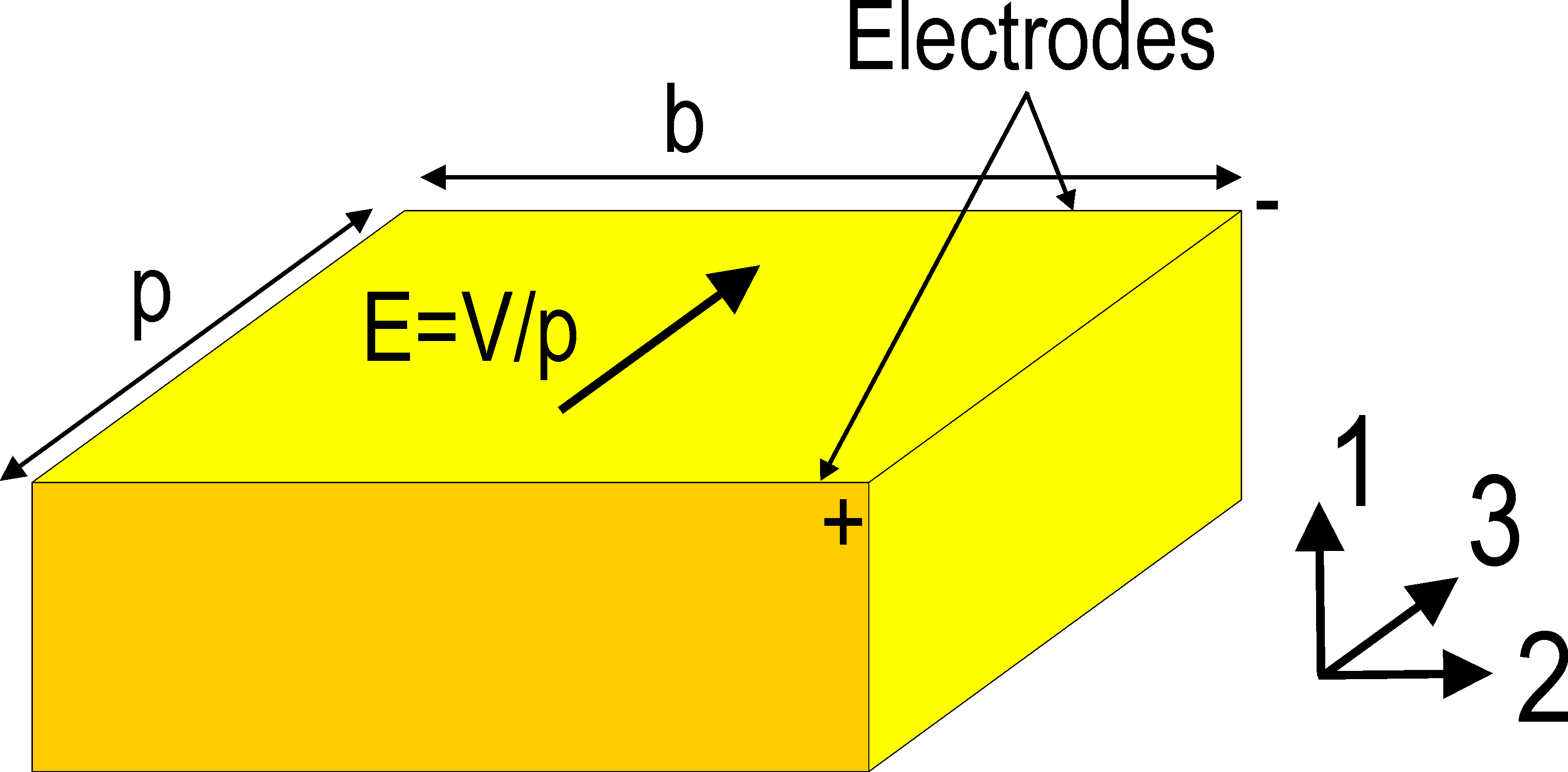
Piezoelectric plate elements implemented in SDT are based on the hypothesis that the poling direction is through the thickness, which is suitable for the P2-type MFCs, but not for the P1-types. It is possible however with a simple analogy to model a P1-type MFC using the piezoelectric plate elements of SDT. The analogy is based on the equality of free in-plane strain of the transducer due to an applied voltage and capacitance. This requires two steps. The first one is to replace the curved electric field lines by a uniform field aligned with the poling direction, equal to E=V/p where p is the distance between the fingers of the interdigitated electrodes (Figure 2.22).
| Figure 2.22: The curved electric field can be replaced by an equivalent electric field E=V/p |
The second step is to express the equivalence in terms of free strains taking into account the difference of local axes (this is because direction 3 is the poling direction which is different in both cases, see Figure 2.23).
As the thickness of the patch h is generally different from the distance between the fingers of the inter-digitated electrodes p, a h/p factor must be used. For MFCs, h=0.180 mm and p=0.500 mm so that h/p= 0.36. The PZT material used in MFCs has properties similar to the Ceramtec P502 material described in Section section 1.2.3. If we assume that the active layer of the MFC is made of a bulk piezoceramic of that type, the equivalent d31 is given by :
This value is lower than the d31 coefficient of the bulk ceramic (185 pC/N). This shows that although the d33 coefficient is larger, the spacing of the fingers of IDE reduces the equivalent strain per Volt (ppm/V). This spacing cannot however be made much smaller as the part of the electric field aligned with the plane of the actuator would be significantly reduced. These findings are confirmed by the tabulated values of free strain per volt (ppm/V) in the fiber direction given in the datasheet of MFCs. Note that because the limiting value for actuation is the electric field and not the voltage, the P1-type MFCs have a much higher maximum voltage limit (1500 V) than the P2-type MFCs (360 V), leading to the possibility to achieve higher free strain, but at the cost of very high voltage values.
Similarly, the dielectric permittivity must be adapted to model P1-type MFCs using an equivalent P2-type MFC. This is done by expressing the equality of the capacitance:
a) b)
| Figure 2.23: Electric fields and local axes used to model a P1-type MFC (b) with an equivalent P2-type MFC (a) |
The fact that piezoelectric fibers are mixed with an epoxy matrix introduces some orthotropy both at the mechanical and the piezoelectric levels. This means that all the parameters of the compliance matrix of an orthotropic material (29) must be identified, together with all piezoelectric coefficients (14). As we are integrating these transducers in plate structures, and assuming that the poling is in the direction of the thickness with electrodes on top and bottom of the piezoelectric layers, the compliance matrix reduces to:
with νyx/Ey= νxy/Ex, the matrix of piezoelectric coefficients to:
and the matrix of dielectric permittivities to a scalar:
In order to model such orthotropic transducers, it is therefore necessary to have access to 6 mechanical properties Ex,Ey, νxy, Gxy, Gxz, Gyz, two piezoelectric coefficients d31, d32, and one dielectric constant є33T. In the following, direction x will be replaced by L standing for 'longitudinal' (i.e. in the fiber direction) and y by T for 'transverse' (i.e. perpendicular to the fiber direction).
As there are no established and standardised techniques for testing piezocomposite transducers and identifying their full set of properties, it is common to find only a limited set of these coefficients in the datasheet of manufacturers. In addition, when such properties are given, they are measured on the full packaged piezocomposite transducer, which makes it difficult to translate them to the properties of each layer without making strong assumptions. The strategy adopted in this tutorial is to consider that an MFC is made of 5 layers (Figure 2.24). The electrode layer is slightly orthotropic due to the presence of the copper, but this effect can be neglected as it does not influence the overall behavior of the transducer. The 4 outer layers are therefore considered as homogeneous layers with the properties given in Table 2.2.
| Figure 2.24: A MFC can be modeled as a 5-layer composite with an inner active layer and four passive layers |
| Material property | value | unit |
| Epoxy |
| E | 2.6 | GPa |
| ν | 0.33 | |
| ρ | 1500 | kg/m3 |
| Kapton |
| E | 2.8 | GPa |
| ν | 0.3 | |
| ρ | 1580 | kg/m3 |
| Table 2.2: Mechanical properties of the passive layers of MFCs |
The mechanical, piezoelectric and dielectric properties of the active layers can be computed from their constituents using piezoelectric homogenization, assuming that the PZT material is Ceramtec P502, the matrix is epoxy with the properties given in Table 2.2, and the volume fraction of fibers is 86%. An analytical approach validated with detailed numerical computations has been developed in [] and []. The homogenized properties found in these studies are given in Tables 2.3 and 2.4. They correspond to the MFC_P2_AL and MFC_P1_AL properties in m_piezo Database. For the P1-type MFCs, the values from Table 2.4 have been corrected with the h/p factor for the piezoelectric properties, and the (h/p)2 factor for the dielectric constant. A value of h/p=0.36 has been used.
|
| | | | |
| P2 MFC Homogenized Properties | Symbol | Unit | Mixing rules |
| | | | |
|
| | | | |
| Young's modulus | EL | GPa | 47.17 |
| | ET | GPa | 16.98 |
| Shear Modulus | GLT | GPa | 6.03 |
| | GTz | GPa | 6.06 |
| | GLz | GPa | 17.00 |
| Poisson's ratio | νLT | - | 0.395 |
| Piezoelectric charge constants | d31 | pC/N | -183 |
| | d32 | pC/N | -153 |
|
Dieletric relative constant (free) | є33T/є0 | - | 1600 |
| | | | |
|
| Table 2.3: Homogenized properties of the active layer of
P2-MFCs calculated using the analytical mixing rules of
[] |
|
| | | | |
| P1 MFC Homogenized Properties | Symbol | Unit | Mixing rules |
| | | | |
|
| | | | |
| Young's modulus | EL | GPa | 42.18 |
| | ET | GPa | 16.97 |
| Shear Modulus | GLT | GPa | 6.03 |
| | GTz | GPa | 17 |
| | GLz | GPa | 6.06 |
| Poisson's ratio | νLT | - | 0.380 |
| Piezoelectric charge constants | d32 | pC/N | -176 |
| | d33 | pC/N | 436 |
| Dieletric relative constant (free) | є33T/є0 | - | 1593 |
| | | | |
|
| Table 2.4: Homogenized properties of the active layer of
P1-MFCs calculated using the analytical mixing rules of [] (correction factor not included)
|
2.3.2 Example of MFC transducers integrated in plate structures
This example deals with a cantilever aluminum plate with two P1-type MFCs (M8528-P1) attached on each side of the plate. The geometry is represented in Figure 2.25. The meshing procedure for the integration of MFC patches is detailed in Section 2.1.3. The plate is meshed with rectangular piezoelectric elements. The main part of the beam is made of one layer (aluminum), and the part where the two MFCs are attached is made of 11 layers (5 layers for each MFC and the central aluminum layer).
| Figure 2.25: Geometric details of the aluminum plate with 2 P1-type MFCs |
( d_piezo('TutoPlate_mfc-s1')
)
model=d_piezo('MeshMFCplate -cantilever');
cf=feplot(model); fecom('colordatagroup-EdgeAlpha.1');
Using the two MFCs as actuators, we define two combinations in order to induce bending or traction and compute and represent the static response (Figure 2.26):
( d_piezo('TutoPlate_mfc-s2')
)
r1=p_piezo('electrodedof',model);
data.def=[1 -1;1 1]';
data.lab={'V-bend';'V-Tract'};
data.DOF=vertcat(r1{:,2})+.21;
model=fe_case(model,'DofSet','V_{In}',data);
model.Stack{strcmpi(model.Stack(:,2),'Electrodes'),3}.ver=1;
nd1=feutil('find node x==463 & y==50',model);
nd2=feutil('find node x==463 & y==0',model);
model=fe_case(model,'SensDof','Tipt-z',nd1+.03);
model=fe_case(model,'SensDof','Tip-x',nd1+.01);
model=fe_case(model,'SensDof','Tipb-z',nd2+.03);
( d_piezo('TutoPlate_mfc-s3')
)
d0=fe_simul('dfrf',stack_set(model,'info','Freq',0));
cf=feplot(model,d0); sens=fe_case(model,'sens');
C1=fe_case('SensObserve -dim 2 3 1',sens,d0);
fecom(';view3;scd .1;colordataEvalA -edgealpha.1;undefline')
a) b)
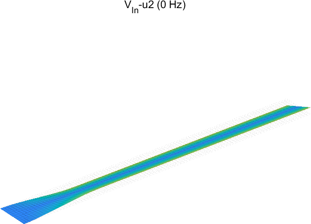
| Figure 2.26: Static deformation under combined voltage actuation in a) bending, b) traction |
The deformed shape under traction actuation highlights the fact that the induced strain in the lateral direction is of opposite sign with respect to the longitudinal direction, which is due to the fact that we are using a P1-type MFC. F1-type MFCs are based on the same layout as P1-types but the fibers are oriented with an angle of 45 . Such transducers can be easily modeled by changing the angle of the active layer in the multi-layer sequence. Assume that the bottom MFC makes an angle of 45 with respect to the axis of the beam and that the top MFC makes an angle of -45 . Each actuator induces both bending and torsion in the plate:
( d_piezo('TutoPlate_mfc-s4')
)
model.il(2,[20 44])=[45 -45];
d1=fe_simul('dfrf',stack_set(model,'info','Freq',0));
cf.def=d1; fecom('scd 10'); C2=fe_case('SensObserve - dim 2 3 1',sens,d1);
The torsion can be easily seen by looking at the deformed shape resulting from the combination of the two MFCs with opposite signs which cancels the bending effect, as shown in Figure 2.27.
| Figure 2.27: Static deformation under combined voltage with opposite sign using two F1-type MFCs |
©1991-2023 by SDTools


 PDF Index
 PDF Index



 d_piezo('TutoPlate_mfc-s1')
)
 d_piezo('TutoPlate_mfc-s2')
)
 d_piezo('TutoPlate_mfc-s3')
)
d_piezo('TutoPlate_mfc-s3')
).png)
.png)
 d_piezo('TutoPlate_mfc-s4')
)