PDF Index
| SDT-visc
Contents
Functions
PDF Index |
The objective of this section is to illustrate strategy proposed to mesh a composite blade possibly containing viscoelastic patches. One starts from
sdtweb d_mesh NacaSkin % see also meshing steps that were used
xxx the ability to use lsutil to generate cuts at target thickness.
d_visco.tutocompply.init : possibly reload
%% Step init : possibly reload
% keywords{var{},fcn{sdtu.f.safe,sdtu.logger.status,sdth.sfield}}
f1=sdtu.f.safe('@tempdir/sdtdemos/d_visco_compPly.mat');
sdtu.logger.status('CmdDisp','on');% Turn logViewer on
if exist(f1,'file')
 load(f1,'RA');RA=sdth.sfield('rename;',RA,{'nmap','projM'});
end

if 1==2
    sdtweb t_4sheet docstring
   sdtu.logger.status('CmdDisp','on');
   d_visco keywords
   sdtweb _taglist sdtu.f % Generate idx and thus DocString graphs
end
name
cat
ToolTip
m
html
TeX
sdtu_f.safe
fcn
safe
html
sdtu_logger.status
fcn
status
html
sdth.sfield
fcn
sfield
m
html
TeX
Step d_visco.tutocompply.mesh : initial mesh generation
%% Step mesh : initial mesh generation
% keywords{var{plyList,MacroLayer,PrePl},fcn{sdtu.fe.boxMacroPly}}

f1=sdtu.f.safe('@tempdir/sdtdemos/d_visco_compPly.mat');
sdtu.logger.status('CmdDisp','on');% Turn logViewer on
if exist(f1,'file')
 load(f1,'RA');RA=sdth.sfield('rename;',RA,{'nmap','projM'});
else;
 RA=d_mesh('nmap.Naca');
 RA.nmap('CurExp')={'MeshCfg{d_mesh(Naca{HyFoilA,zs.1,yn1,unitmm}):empty}','RunCfg{feplot(2)}'};
 sdtm.range.RA); RA=sdth.sfield('rename;',RA,{'nmap','projM'});
 remove(RA.projM,'cf');sdtm.store.f1,'RA>RA')
end

% Define names for each area
mo3=RA.projM('area');if ~isfield(mo3,'nmap');mo3.nmap=vhandle.nmap;end
proM=mo3.nmap('Map:SetName');proM.append({'Pro:1','A1';'Pro:2','A2';'Pro:3','A3'})

% Define the FootStart line as a set in area for later extension
mo3=feutil('addset NodeId',mo3,'FootStart','linetopo{starts 1 32,cos .9}');

RA.projM('PlyDef')=struct( ...
'plyList', ... % define ply list
  {{'PlyNum','PlyMat','Thick','Orient','sel'
     1,  'X', 0.5, 0,'ProName"(A1|A2|A3)"'
     2,  'U', 1,   0,'ProName"(A1|A2|A3)"'
     3,  'U', 1,  90,'ProName"(A2|A3)"'
     4,  'Y', Inf,   0,'ProName"(A2|A3)"'
     5,  'U', 1,  90,'ProName"(A2|A3)"'
     6,  'U', 1,   0,'ProName"(A1|A2|A3)"'
     7,  'X', 0.5, 0,'ProName"(A1|A2|A3)"'
     }},...
 'MacroLayer', ...  % define macro layers
    {{'Name','MacroPly','Plies', 'Area','ProIdOut';
     'A1Top', 1,        [  1 2], 'A1',1001;
     'A2Top', 1,        [1 2 3], '(A2|A3)',[1002 1003];
     'Insert',2,             4 , 'A3',     2003
     'Fill',  2,             4 , '(A1|A2)',[2001 2002]
     'A1Bot',3,           [6 7], 'A1',   3001;
     'A2Bot', 3,        [5 6 7], '(A2|A3)',[3002 3003]
     }}, ...
'PrePl', ... % define ply materials
  {{'name','X','U','Y';
   'MatId',30,31,32;
   'color','Coral','OrangeRed','DarkOrange';
   'E1',60e3,30e3,14e3;
   'E2',4e3,30e3,14e3;
   'E3',4e3,9e3,7e3;
   'nu12',.3,0.04,0.3;
   'nu13',.3,0.4,0.3;
   'nu23',0.488,0.4,0.35;
   'G12',2e3,2e3,5e3;
   'G13',2e3,2e3,2e3;
   'G23',2e3,2e3,2e3;
   'Rho',1400e-9,1400e-9,1500e-9}});

mo3=sdtu.fe.boxMacroPly(mo3,RA.projM('PlyDef'));mo3.name='area';
RA.projM(mo3.name)=mo3;
fevisco('MeshPliesViewH',mo3) % 'xxx document error on thickness on layer edges'

if sdtweb('_TutoNeed','figgen')
 cf=feplot(2,';');cf.mdl=RA.projM('area');fecom showfipro
 comgui('imwrite',2,'@tempdir/sdtdemos/plots/d_visco_TutoCompPly_StepMesh.png')
 sdtu.ui.tabChange('SDT Root.Tab.PlyList');gf=gcf;
 cingui('objset',gf,{'Position',[NaN NaN 592 236]})
 comgui('imwrite',gcf,struct('Java',5,'FileName','@tempdir/sdtdemos/plots/d_visco_TutoCompPly_TabPlyList.png'))
 sdtu.ui.tabChange('SDT Root.Tab.PlyList');gf=gcf;
 comgui('imwrite',gcf,struct('Java',5,'FileName','@tempdir/sdtdemos/plots/d_visco_TutoCompPly_TabMacroLayer.png'))
 ta=sdtu.ui.tabChange('SDT Root.Tab.PlyList');ta=ta.Source;
 ta.param.colM.prop('PlyNum').fmt='%i';
 ta.param.colM.prop('Thick').fmt='%.1f';
 asTex(ta)
end
if sdtweb('_TutoNeed','check')
 % if ~isequal()  sdtm.Hash('reproducible',)
end
name
cat
ToolTip
m
html
TeX
plyList
var
\hypertarget{var.plyList}
TeX
MacroLayer
var
\hypertarget{var.MaCroLayer}
TeX
PrePl
var
var.PrePl
html
sdtu_fe.boxMacroPly
fcn
boxMacroPly
html
 mesh
illustrates the proposed strategy,
mesh
illustrates the proposed strategy,
The plyList table gives the relation between ply numbers, the associated material PlyMat, thickness, material orientation with respect to the local xe,ye plane, and selection (see findElt ) of area whose elements are covered by a given ply. The inf in the Y layer indicates that its thickness is variable the insert in this case.
| PlyNum | PlyMat | Thick | Orient | sel |
| 1 | X | 0.5 | 0 | ProName"(A1|A2|A3)" |
| 2 | U | 1.0 | 0 | ProName"(A1|A2|A3)" |
| 3 | U | 1.0 | 90 | ProName"(A2|A3)" |
| 4 | Y | Inf | 0 | ProName"(A2|A3)" |
| 5 | U | 1.0 | 90 | ProName"(A2|A3)" |
| 6 | U | 1.0 | 0 | ProName"(A1|A2|A3)" |
| 7 | X | 0.5 | 0 | ProName"(A1|A2|A3)" |
To allow the automated definition of macro plies (volume element combining multiple plies), the MaCroLayer table then gives the name of macro areas, the index of each macro ply, the plies associated with a selected area, and the property number associated with
| Name | MacroPly | Plies | Area | ProIdOut |
| A1Top | 1 | 1 2 | A1 | 1001 |
| A2Top | 1 | 1 2 3 | (A2|A3) | 1002 1003 |
| Insert | 2 | 4.0 | A3 | 2003 |
| Fill | 2 | 4.0 | (A1|A2) | 2001 2002 |
| A1Bot | 3 | 6 7 | A1 | 3001 |
| A2Bot | 3 | 5 6 7 | (A2|A3) | 3002 3003 |
Finally, the PrePl table gives elastic properties of plies as shown below. This is then used to define an orthotropic material for each macro ply using KUBC homogeneisation [48].
| name | X | U | Y |
| MatId | 30.0 | 31.0 | 32.0 |
| color | Coral | OrangeRed | DarkOrange |
| E1 | 60000.0 | 30000.0 | 14000.0 |
| E2 | 4000.0 | 30000.0 | 14000.0 |
| ⋮ | ⋮ | ⋮ | ⋮ |
xxx texSafeCell
d_visco('TutoCompPly -s{Mesh,SplitSkin} -show -reset -need{figgen,check};') xxxgv/gm revise two icons to run/open code.
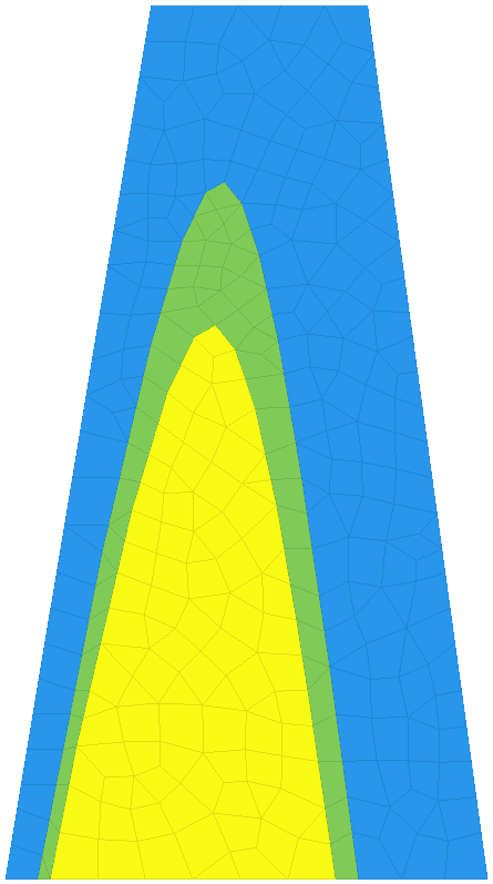
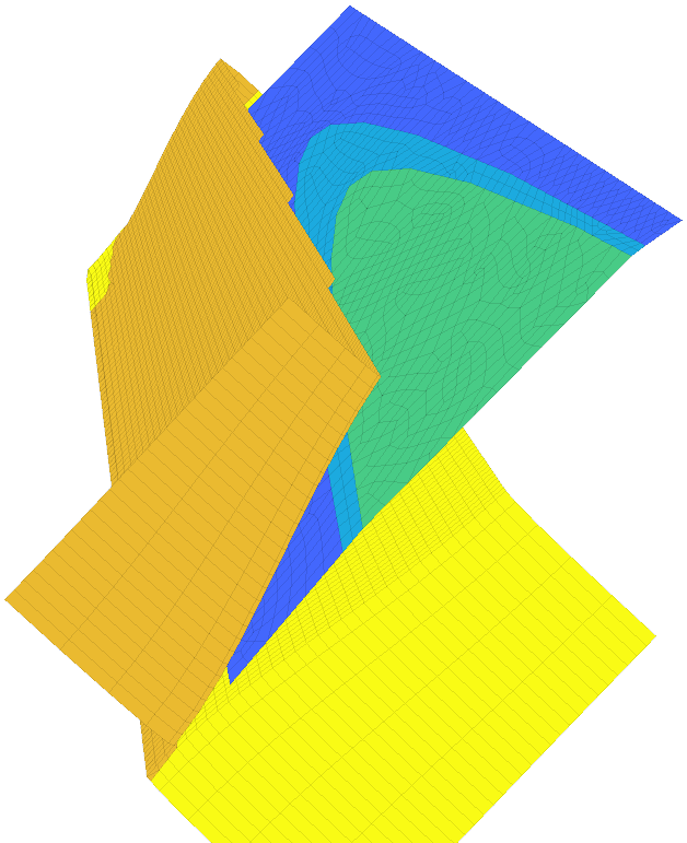
Step boxInSkin then projects the area onto the surface. This generates a topological box where there is one hexa8 element through the thickness. Topological box meshes can be used for surfaces quad4 or volumes hexa8.
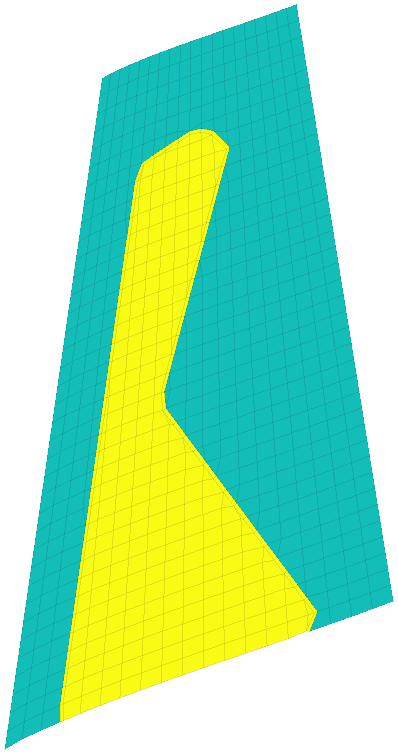
MeshLayerV2
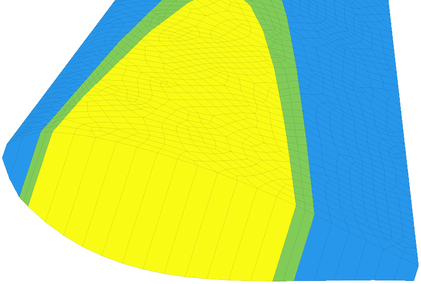
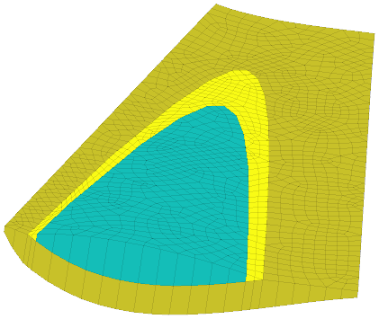
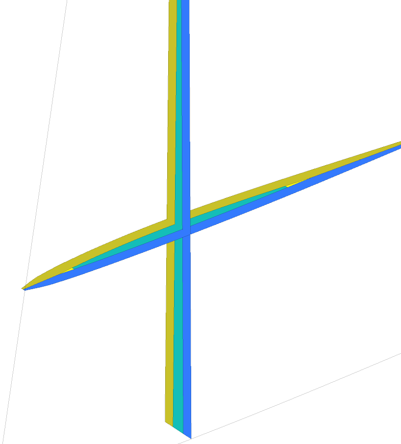
Figure 3.3: Left : initial box, center : layer meshes with insert in green, fill in yellow and top layer in xxxGV revise assignation of colors Map:ProColor . Right : horizontal and vertical cuts of the mesh.
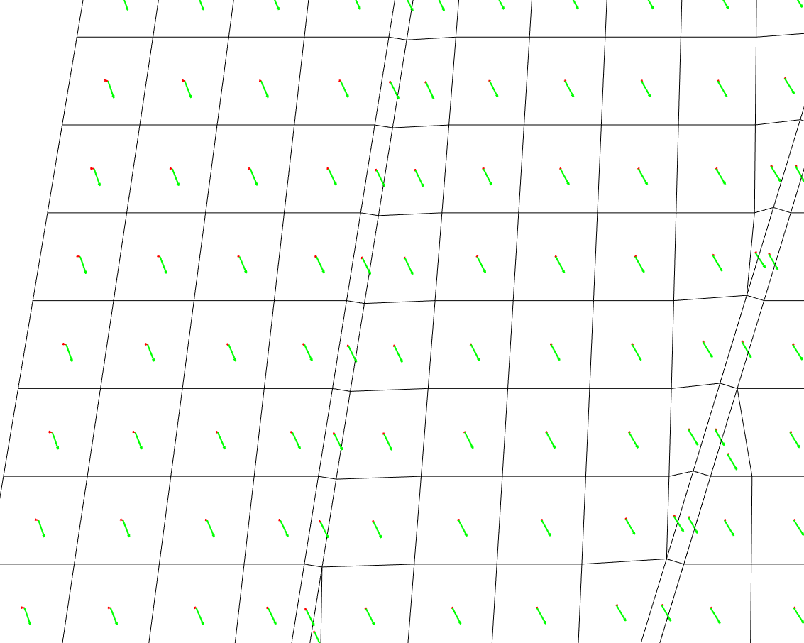
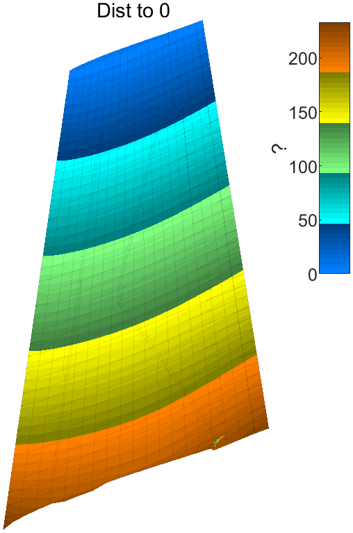
Step RSZMap
defines distance maps that will later be used for foot meshing.
struct('distFcn','fe_shapeoptim','model','skin', ...
'SurfSel','matid 101','OrientLine','z>50');
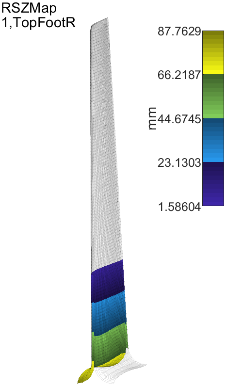
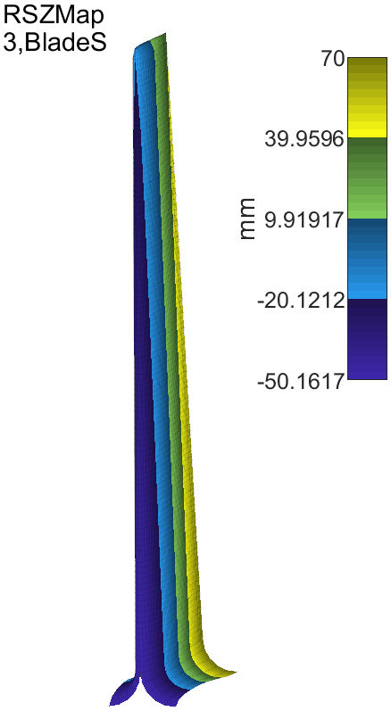
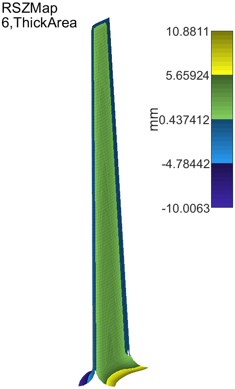
Figure 3.4: Definition of coordinate maps
Step MeshRS
extends the .area='MacroVol' on the skin with distance maps .skin='RSZMap' xxx 'RSZMap'. An extension is built by giving the following parameters
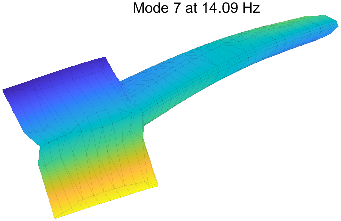
Figure 3.5: Extended mesh with foot defined
xxx
As the ply definition area does not go to the foot (the skin in figure 3.2 larger), a transition is needed.
To achieve this mesh while following the skin with controlled thickness, one uses a geometric mapping. An r coordinate is set at zero using
StepArea illustrates the ability to use a contour to locally remesh a patch. To allow thickness transitions, the boundary between interior and exterior is meshed using quads. StepOrientArea illustrates the ability to define material orientations, which is needed for composites
A1L1 : edge only one multiply layup
A2L1 : lower face A2L2 : core A2L3 : upper face
A3L1 : lower face A3L2 : core A3L3 : between core and visco A3L4 : visco A3L5 : between visco and upper face
xxxEB Step FootTransition
xxxEB Step OrientSensitivity : xxx sensitivity to material orientation xxx