
 PDF Index
|
Contents
Functions
PDF Index |
Gateway function for 3-D visualization of structures. See also the companion function fecom.
Syntax
feplot
feplot(FigHandle)
feplot(model)
feplot(model,def)
Description
fecom gives a complete list of commands. The rest of this section gives more details on the feplot architecture. For a tutorial see section 4.4. Basic ways to call feplot are
The old formats feplot(node,elt,mode,mdof,2) and cf.model={Node,Elt} are still supported but you are encouraged to switch to the new and more general procedure outlined above.
Views of deformed structures are obtained by combining information from various data arrays that can be initialized/modified at any time. The object hierarchy is outlined below with the first row being data arrays that store information and the second row objects that are really displayed in MATLAB axes.
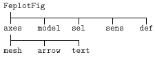
axes describe axes to be displayed within the feplot figure. Division of the figure into subplots (Matlab axes) is obtained using the fecom Sub commands. Within each plot, basic displays (wire mesh, surface, sensor, arrow corresponding to mesh, arrow, or text objects) can be obtained using the fecom Show commands while more elaborate plots are obtained using fecom SetObject commands. Other axes properties (rotations, animation, deformation selection, scaling, title generation, etc.) can then be modified using fecom commands.
| mdl | Model data structure (see section 7.6) cf.mdl is a handle to the model contained in the feplot figure. The model must be defined before any plot is possible. It is initialized using the fecom InitModel command or using the method cf.model. |
| Stack | Model Stack entries are stored in cf.mdl.Stack, but can be more easily reached using cf.Stack{i} or cf.Stack{EntryName} or modified using cf.Stack{EntryType,EntryName}=EntryData. |
| CStack | Case Stack entries are stored in the stack case (itself stored in cf.mdl.Stack). They can be more easily reached using cf.CStack{i} or cf.CStack{EntryName} or modified using cf.CStack{EntryType,EntryName}=EntryData. |
| sel | Element selections describe which elements are displayed. The standard selection displays all elements of all groups. fecom Sel commands or cf.sel(i) let you define selections that only display some elements. See also the fecom SetObject commands. Color information is defined for each selection (see fecom Color commands). cf.sel(i)= 'ElementSel' initializes a selection to use element selected by ElementSel. Note that you may want to declare color data simultaneously using cf.sel(i)= {'ElementSel','Colordata Command',Args}. cf.o(i)= {'ObjectSpec','PatchProperty',PatchValue} modifies the properties of object i in the current feplot axis. |
| sens | (obsolete) sensor selections describe sets of sensors. Sensor selections are used to display the response at measurement locations through stick or arrows. Initialized using the InitSens command or cf.sens(i) calls (see fecom).cf.sens(i)={sdof} initializes a sensor set (see fecom InitSens). |
| def | deformation sets describe deformations at a number of DOFs. Initialized using the InitDef command or cf.def(i) calls (see fecom). cf.def(i)={def,dof} is also accepted. cf.def(i)={def,dof,freq} where freq is a list of frequencies of poles automatically generates title labels for each deformation (see fecom InitDef). |
Objects
mesh objects represent a deformed or undeformed finite element mesh. They are used both for wire-frame and surface representations. mesh objects are characterized by indices giving the element selection, deformation set, channel (deformation number), and color type. They can be modified using calls or the form
 cf = feplot; % get sdth object handle
 cf.o(2) = 'sel 1 def 1 ch 3'
or equivalently with fecom SetObject commands. fecom Show commands reset the object list of the current axis.
Each mesh object is associated to up to three MATLAB patch objects associated respectively with real surfaces, segments and isolated nodes. You can access individual pointers to the patch objects using cf.o(i,j) (see fecom go commands).
Arrow objects are used to represent sensors, actuators, boundary conditions, ... They are characterized by indices giving their sensor set, deformation set, channel (deformation number), and arrow type. They can be modified using calls or the form (see fecom SetObject commands)
 cf = feplot; % get sdth object handle
 cf.o(2) = 'sen 1 def 1 ch 3'
The SDT currently supports stick sensors (object type 3) and arrows at the sensor tip (type 7). Other arrow types will eventually be supported.
fecom text objects are vectorized lists of labels corresponding to nodes, elements, DOFs, ... They can be initialized using fecom Text commands and deleted with textoff. You can use cf.o(i) (see fecom go commands) to get handles to the associated MATLAB text objects and thus set font name size, ... set(cf.o(1), 'fontsize', 7) for example.
Data arrays
feplot stores information in various data arrays cf.mdl for the model, cf.def(i) for the definition of deformations, cf.sel(i) for element selections for display and cf.sens(i) for sensor selections.
The model currently displayed is stored in cf.mdl, see fecom InitModel.
The cf.data field is used to store volatile interface data. In particular .ViewClone can store axes handles that should keep synchronized orientations.
The deformations currently displayed are stored in cf.def, see fecom InitDef for accepted input formats.
element selections describe a selection of elements to be displayed. The standard selection displays all elements of all groups. fecom Sel commands let you define selections that only display some elements.
| .selelt | string used for element selection |
| .vert0 | position of vertices (nodes) in the undeformed configuration |
| .node | node numbers associated to the various vertices |
| .cna | array (as many as currently declared deformations) of sparse observation matrices giving the linear relation between deformation DOFs and translation DOFs at the selection nodes. The observation matrix gives all x translations followed by all y translations and all z translations. |
| .fs | face definitions for true surfaces (elements that are not represented by lines or points). .ifs gives the element indices (possibly repeated if multiple faces) |
| .f2 | face definitions for lines (if any). .if2 gives the element indices (possibly repeated if multiple faces). |
| .f1 | face definitions for points (if any). |
| .fvcs | FaceVertexCData for true surfaces (see fecom ColorData commands). Can also be a string, which is then evaluated to obtain the color, or a function handle used in ColorAnimFcn. |
| .fvc2 | FaceVertexCData for lines |
| .fvc1 | FaceVertexCData for points |
sensor selections describe sets of sensors. Sensor selections are used to display the response at measurement locations through stick or arrows. The InitSens command is being replaced by the definition of SensDof stack entries.
| .vert0 | position of vertices (nodes) in the undeformed configuration |
| .node | node numbers associated to the various vertices |
| .ntag | numerical tag identifying each sensor |
| .dir | direction associated with each sensor |
| .cta | array (as many as currently declared deformations) of sparse observation matrices giving the linear relation between deformation DOFs and measurements. |
| .opt | [Created] |
| .arrow | defines how the arrow is related to the measurement |
See also
fecom, femesh, feutil, tutorial in section 4.4
