
 PDF Index
|
Contents
Functions
PDF Index |
In this section one describes the developments needed to integrate a new element function into OpenFEM. First, general information about OpenFEM work is given. Then the writing of a new element function is described. And at last, conventions which must be respected are given.
To improve the ease of development of new elements, OpenFEM now supports a new category of generic element functions. Matrix assembly, stress and load assembly calls for these elements are fully standardized to allow optimization and generation of new element without recompilation. All the element specific information stored in the EltConst data structure.
Second generation volume elements are based on this principle and can be used as examples. These elements also serve as the current basis for non-linear operations.
The adopted logic is to develop families of elements with different topologies. To implement a family, one needs
The following sections detail the principle for linear and non-linear elements.
Most of the work in defining a generic element is done in the element property function (for initializations) and the compile of_mk function. You do still need to define the commands
 if comstr(Cam,'integinfo')
  %constit integ,elmap                       ID,pl,il
  [out,out1,out2]= ...
   p_solid('buildconstit',[varargin{1};24;8],varargin{2},varargin{3});
input arguments passed from fe_mknl are ID a unique pair of MatId and ProId in the current element group. pl and il the material and element property fields in the model. Expected outputs are constit, integ and elmap, see Case.GroupInfo. Volume elements hexa8, q4p, ... are topology holders. They call p_solid BuildConstit which in turn calls as another property function as coded in the type (column two of il coded with fe_mat('p_fun','SI',1)). When another property function is called, it is expected that constit(1:2)=[-1 TypeM] to allow propagation of type information to parts of the code that will not analyze pl.
...
elseif comstr(Cam,'constants')
  integ=varargin{2};constit=varargin{3};
  if nargin>3; [out,idim]=p_solid('const','hexa8',integ,constit);
  else; p_solid('constsolid','hexa8',[1 1 24 8],[]);return;
  end
  out1=varargin{1};out1(4,:)=idim; % Tell of_mk('MatrixInt') this is IDIM
...
input arguments passed from fe_mknl are pointers,integ,constit the output arguments are EltConst and a modified pointers where row 4 is modified to specify a 3D underlying geometry.
If constit(1:2)=[-1 TypeM] p_solid calls the appropriate property function.
For elements that have an internal orientation (shells, beams, etc.) it is expected that orientation maps are built during this command (see beam1t, ...). Note, that the 'info','EltOrient' stack entry can also be used for that purpose.
hexa8 provides a clean example of what needs to be done here.
p_fcn
Commands specific to p_* are associated to the implementation of a particular physical formulation for all topologies.
As shown in section 7.15.1 and detailed under fe_mknl the FEM initialization phase needs to resolve
Many aspects of a finite element formulation are independent of the supporting topology. Element property functions are thus expected to deal with topology independent aspects of element constant building for a given family of elements.
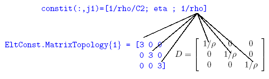
Thus the element integinfo call usually just transmits arguments to a property function that does most of the work. That means defining the contents of integ and constit columns. For example for an acoustic fluid, constit columns generated by p_solid BuildConstit contain [1/ρ C2 η 1/ρ].
Generic elements (hexa8, q4p, ...) all call p_solid BuildConstit. Depending on the property type coded in column 2 of the current material, p_solid attempts to call the associated m_mat function with a BuildConstit command. If that fails, an attempt to call p_mat is made (this allows to define a new family of elements trough a single p_fcn p_heat is such an example).
integ nominally contains MatId,ProId,NDofPerElt,NNodePerElt,IntegRuleNumber.
Similarly, element constant generation of elements that support variable integration rules is performed for an element family. For example, p_solid const supports for 3D elastic solids, for 2D elastic solids and 3D acoustic fluid volumes. p_heat supports 2D and 3D element constant building for the heat equation.
Generic elements (hexa8, q4p, ...) all use the call
[EltConst,NDNDim] = p_solid('Const',ElemF, integ, constit).
User extendibility requires that the user be able to bypass the normal operation of p_solid const. This can be achieved by setting constit(1)=-1 and coding a property type in the second value (for example constit(1)=fe_mat('p_heat','SI',1). The proper function is then called with the same arguments as p_solid.
*_fcn
Expected commands common to both p_* and m_* functions are the following
With no argument returns a cell array of strings associated with each subtype (maximum is 9). With a string input, it returns the numeric value of the subtype. With a numeric input, returns the string value of the subtype. See m_elastic for the reference implementation.
Returns a structure with reference materials or properties of this type. Additional strings can be used to give the user more freedom to build properties.
Mostly the same as database but replaces or appends rows in model.il (for element properties) or model.pl (for material properties).
i1=p_function('PropertyUnitType',SubType) returns for each subtype the units of each value in the property row (column of pl).
This mechanism is used to automate unit conversions in fe_mat Convert.
[list,repeat]=p_function('PropertyUnitTypeCell',SubType) returns a cell array describing the content of each column, the units and possibly a longer description of the variable. When properties can be repeated a variable number of times, use the repeat (example in p_shell for composites). This mechanism is used to generate graphical editors for properties.
Cell arrays describing each subtype give
of_mk is the C function used to handle all compiled element level computations. Integration rules and shape derivatives are also supported as detailed in BuildNDN.
This element family supports a fairly general definition of linear multi-physic elements whose element integration strategy is fully described by an EltConst data structure. hexa8 and p_solid serve as a prototype element function. Element matrix and load computations are implemented in the of_mk.c MatrixIntegration command with StrategyType=1, stress computations in the of_mk.c StressObserve command.
EltConst=hexa8('constants',[],[1 1 24 8],[]);
integrules('texstrain',EltConst)
EltConst=integrules('stressrule',EltConst);
integrules('texstress',EltConst)
Elements of this family are standard element functions (see section 7.16) and the element functions must thus return node, prop, dof, line, patch, edge, face, and parent values. The specificity is that all information needed to integrate the element is stored in an EltConst data structure that is initialized during the fe_mknl GroupInit phase.
For DOF definitions, the family uses an internal DOF sort where each field is given at all nodes sequentially 1x 2x ... 8x 1y ... 8 y ... while the more classical sort by node 1x 1y ... 2x ... is still used for external access (internal and external DOF sorting are discussed in section 7.16.6).
Each linear element matrix type is represented in the form of a sum over a set of integration points
| (7.12) |
where the jacobian of the transformation from physical xyz to element rst coordinates is stored in EltConst.jdet(jw) and the weighting associated with the integration rule is stored in EltConst.w(jw,4).
The relation between the Case.GroupInfo constit columns and the Dij constitutive law matrix is defined by the cell array EltConst.ConstitTopology entries. For example, the strain energy of a acoustic pressure formulation (p_solid ConstFluid) is given by
The integration rule for a given element is thus characterized by the strain observation matrix Bji(r,s,t) which relates a given strain component єji and the nodal displacements. The generic linear element family assumes that the generalized strain components are linear functions of the shape functions and their derivatives in euclidian coordinates (xyz rather than rst).
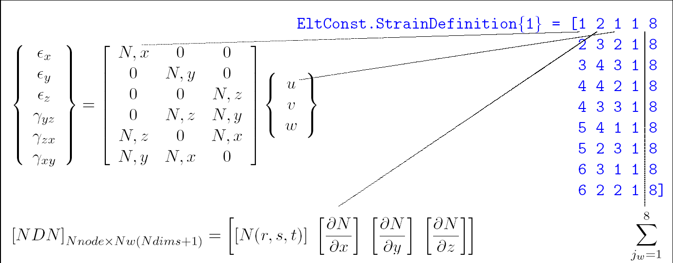
The first step of the element matrix evaluation is the evaluation of the EltConst.NDN matrix whose first Nw columns store shape functions, Nw next their derivatives with respect to x, then y and z for 3D elements
| (7.13) |
To improve speed the EltConst.NDN and associated EltConst.jdet fields are preallocated and reused for the assembly of element groups.
For each strain vector type, one defines an int32 matrix
EltConst.StrainDefinition{jType} with each row describing row, NDNBloc, DOF, NwStart, NwTot giving the strain component number (these can be repeated since a given strain component can combine more than one field), the block column in NDN (block 1 is N, 4 is ∂ N/∂ z, a negative number can be used to specify −N, ...), the field number, and the starting integration point associated with this strain component and the number of integration points needed to assemble the matrix. The default for NwStart NwTot is 1, Nw but this formalism allows for differentiation of the integration strategies for various fields. The figure below illustrates this construction for classical mechanical strains.
To help you check the validity of a given rule, you should fill the
EltConst.StrainLabels{jType} and EltConst.DofLabels fields and use the
integrules( 'texstrain', EltConst) command to generate a LATEX printout of the rule you just generated.
The .StrainDefinition and .ConstitTopology information is combined automatically in integrules to generate .MatrixIntegration (integrules MatrixRule command) and .StressRule fields (integrules StressRule command). These tables once filed properly allow an automated integration of the element level matrix and stress computations in OpenFEM.
The core of element computations is the matrixintegration command that computes and assembles a group of elements.
After a number of inits, one enters the loop over elements.
The nodeE matrix, containing field at element nodes, is filled with information at the element nodes as columns. The first 3 columns are positions. Column 4 is reserved for node numbers in case a callback to MATLAB makes use of the information. The following columns are based on the InfoAtNode structure whos indexing strategy is compatible with both continuous and discontinuous fields at each node. See sdtweb elem0('get_nodeE') for details.
Initialization of InfoAtNode is performed with fe_mknl('Init -gstate') calls. The m_elastic AtNodeGState command is an illustration of init used to interpolate material properties in volume elements.
The defe vector/matrix contains the values at the current element DOF of the provided deformation(s).
Right hand side (load) computations can either be performed once (fixed set of loads) through fe_load which deals with multiple loads, or during an iterative process where a single RHS is assembled by fe_mknl into the second column of the state argument dc.def(:,2) along with the matrices when requiring the stiffness with MatDes=1 or MatDes=5 (in the second case, the forces are assumed following if implemented).
There are many classical forms of RHS, one thus lists here forms that are implemented in of_mk.c MatrixIntegration. Computations of these rules, requires that the EltConst.VectMap field by defined. Each row of EltConst.RhsDefinition specifies the procedure to be used for integration.
Two main strategies are supported where the fields needed for the integration of loads are stored either as columns of dc.def (for fields that can defined on DOFs of the model) or as nodeE columns.
Currently the only accepted format for rows of EltConst.RhsDefinition is
101(1) InfoAtNode1(2) InStep(3) NDNOff1(4) FDof1(5) NDNCol(6)
NormalComp(7) w1(8) nwStep(9)
Where InfoAtNode1 gives the first row index in storing the field to be integrated in InfoAtNode. InStep gives the index step (3 for a 3 dimensional vector field), NDNOff1 gives the block offset in the NDN matrix (zero for the nominal shape function). FDof1 gives the offset in force DOFs for the current integration. NDNCol. If larger than -1, the normal component NormalComp designs a row number in EltConst.bas, which is used as a weighting coefficient. tt w1 gives the index of the first gauss point to be used (in C order starting at 0). nwStep gives the number of gauss points in the rule being used.
| (7.14) |
are thus described by
 opt.RhsDefinition=int32( ...
   [101 0 3 0     0 0 -1    rule+[-1 0];
    101 1 3 0     1 0 -1    rule+[-1 0];
    101 2 3 0     2 0 -1    rule+[-1 0]]);
for 3D solids (see p_solid).
Similarly, normal pressure is integrated as 3 volume forces over 3D surface elements with normal component weighting
| (7.15) |
| (7.16) |
Elastic3DNL fully anisotropic elastic elements in geometrically non-linear mechanics problems. Element matrix are implemented in the of_mk.c MatrixIntegration command with StrategyType=2 for the linear tangent matrix (MatType=5). Other computations are performed using generic elements (section 7.16.4) (mass MatType=2). This formulation family has been tested for the prediction of vibration responses under static pre-load.
Stress post-processing is implemented using the underlying linear element.
Simultaneous element matrix and right hand side computations are implemented in the of_mk.c MatrixIntegration command with StrategyType=3 for the linear tangent matrix (MatType=5). In this case (and only this case!!), the EltConst.NDN matrix is built as follow:
for 1≤ jw ≤ Nw
| (7.17) |
with
| (7.18) |
This implementation corresponds to case 31 of NDNSwitch function in of_mk_pre.c. The purpose is to use C-BLAS functions in element matrix and right hand side computations implemented in the same file (function Mecha3DintegH) to improve speed.
Other computations are performed using generic elements (section 7.16.4) (mass MatType=2). This formulation family has been tested for the RivlinCube test.
Stress post-processing is not yet implemented for hyperelastic media.
Non linear problems are characterized by the need to perform iterations with multiple assemblies of matrices and right hand sides (RHS). To optimize the performance, the nominal strategy for non-linear operations is to
At a given iteration, one resets the RHS and performs a single fe_mknl call that returns the current non-linear matrix and replaces the RHS by its current value (note that fe_mknl actually modifies the input argument dc which is not an normal MATLAB behavior but is needed here for performance)
 % at init allocate DC structure
 dc=struct('DOF',model.DOF,'def',zeros(length(model.DOF),2);
 % ... some NL iteration mechanism here
 dc.def(:,2)=0; % reset RHS at each iteration
 k=fe_mknl('assemble not',model,Case,dc,5); % assemble K and RHS
Most of the work for generic elements is done within the of_mk MatrixIntegration command that is called by fe_mknl. Each call to the command performs matrix and RHS assembly for a full group of elements. Three strategies are currently implemented
Nominally you should write topology independent element families, if hard coding is needed you can however develop new element functions.
In Matlab version, a typical element function is an .m or .mex file that is in your MATLAB path. In Scilab version, a typical element function is an .sci or .mex file that is loaded into Scilab memory (see getf in Scilab on-line help).
The name of the function/file corresponds to the name of the element (thus the element bar1 is implemented through the bar1.m file)
To build a new element take q4p.m or q4p.sci as an example.
As for all Matlab or Scilab functions, the header is composed
of a function syntax declaration and a help section. The following example is written for Matlab. For Scilab version, don't forget to replace % by //. In this example, the name of the created element is elem0.
For element functions the nominal format is
 function [out,out1,out2]=elem0(CAM,varargin);
 %elem0 help section
The element function should then contain a section for standard calls which let other functions know how the element behaves.
 if isstr(CAM) %standard calls with a string command

  [CAM,Cam]=comstr(CAM,1); % remove blanks
  if comstr(Cam,'integinfo')
   % some code needed here
   out= constit; % real parameter describing the constitutive law
   out1=integ;   % integer (int32) parameters for the element
   out2=elmap;

  elseif comstr(Cam,'matcall')
   out=elem0('call');
   out1=1; % SymFlag
  elseif comstr(Cam,'call');     out = ['AssemblyCall'];
  elseif comstr(Cam,'rhscall');  out = ['RightHandSideCall'];
  elseif  comstr(Cam,'scall');   out = ['StressComputationCall'];
  elseif  comstr(Cam,'node');    out = [NodeIndices];
  elseif  comstr(Cam,'prop');    out = [PropertyIndices];
  elseif  comstr(Cam,'dof');     out = [ GenericDOF ];
  elseif comstr(Cam,'patch');
                         out = [ GenericPatchMatrixForPlotting ];
  elseif comstr(Cam,'edge');     out = [ GenericEdgeMatrix ];
  elseif comstr(Cam,'face');     out = [ GenericFaceMatrix ];
  elseif comstr(Cam,'sci_face'); out = [ SciFaceMatrix ];
  elseif comstr(Cam,'parent');   out = ['ParentName'];
  elseif comstr(Cam,'test')
     % typically one will place here a series of basic tests
  end
  return
 end % of standard calls with string command
The expected outputs to these calls are detailed below.
Format string for element matrix computation call. Element functions must be able to give fe_mk the proper format to call them (note that superelements take precedence over element functions with the same name, so avoid calling a superelement beam1, etc.).
matcall is similar to call but used by fe_mknl. Some elements directly call the of_mk mex function thus avoiding significant loss of time in the element function. If your element is not directly supported by fe_mknl use matcall=elem0('call').
The format of the call is left to the user and determined by fe_mk by executing the command eCall=elem0('call'). The default for the string eCall should be (see any of the existing element functions for an example)
  [k1,m1]=elem0(nodeE,elt(cEGI(jElt),:),...
                pointers(:,jElt),integ,constit,elmap);
To define other proper calling formats, you need to use the names of a number of variables that are internal to fe_mk. fe_mk variables used as output arguments of element functions are
| k1 | element matrix (must always be returned, for opt(1)==0 it should be the stiffness, otherwise it is expected to be the type of matrix given by opt(1)) |
| m1 | element mass matrix (optional, returned for opt(1)==0, see below) |
[ElemF,opt,ElemP]=feutil('getelemf',elt(EGroup(jGroup),:),jGroup)
returns, for a given header row, the element function name ElemF, options opt, and parent name ElemP.
fe_mk and fe_mknl variables that can be used as input arguments to element function are listed in section 7.15.2.
Generic DOF definition vector. For user defined elements, the vector returned by elem0('dof') follows the usual DOF definition vector format (NodeId.DofId or -1.DofId) but is generic in the sense that node numbers indicate positions in the element row (rather than actual node numbers) and -1 replaces the element identifier (if applicable).
For example the bar1 element uses the 3 translations at 2 nodes whose number are given in position 1 and 2 of the element row. The generic DOF definition vector is thus [1.01;1.02;1.03;2.01;2.01;2.03].
A dofcall command may be defined to bypass generic dof calls. In particular, this is used to implement elements where the number of DOFs depends on the element properties. The command should always return out=elem0('dofcall');. The actual DOF building call is performed in p_solid('BuildDof') which will call user p_*.m functions if needed.
Elements may use different DOF sorting for their internal computations.
face is a matrix where each row describes the positions in the element row of nodes of the oriented face of a volume (conventions for the orientation are described under integrules). If some faces have fewer nodes, the last node should be repeated as needed. feutil can consider face sets with orientation conventions from other software.
edge is a matrix where each row describes the node positions of the oriented edge of a volume or a surface. If some edges have fewer nodes, the last node should be repeated as needed.
line (obsolete) is a vector describes the way the element will be displayed in the line mode (wire frame). The vector is generic in the sense that node numbers represent positions in the element row rather than actual node numbers. Zeros can be used to create a discontinuous line. line is now typically generated using information provided by patch.
patch. In MATLAB version, surface representations of elements are based on the use of MATLAB patch objects. Each row of the generic patch matrix gives the indices nodes. These are generic in the sense that node numbers represent positions in the element row rather than actual node numbers.
For example the tetra4 solid element has four nodes in positions 1:4. Its generic patch matrix is [1 2 3;2 3 4;3 4 1;4 1 2]. Note that you should not skip nodes but simply repeat some of them if various faces have different node counts.
sci_face is the equivalent of patch for use in the SCILAB implementation of OpenFEM. The difference between patch and sci_face is that, in SCILAB, a face must be described with 3 or 4 nodes. That means that, for a two nodes element, the last node must be repeated (in generality, sci_face = [1 2 2];). For a more than 4 nodes per face element, faces must be cut in subfaces. The most important thing is to not create new nodes by the cutting of a face and to use all nodes. For example, 9 nodes quadrilateral can be cut as follows :

Figure 7.1: Lower order patch representation of a 9 node quadrilateral
but a 8 nodes quadrilaterals cannot by cut by this way. It can be cut as follows:

Figure 7.2: Lower order patch representation of a 8 node quadrilateral
integinfo, BuildConstit are commands to resolve constants in elements and p_function respectively.
[constit,integ,elmap]=elem0('integinfo',[MatId ProId],pl,il,model,Case) is supposed to search pl and il for rows corresponding to MatId and ProId and return a real vector constit describing the element constitutive law and an integer vector integ.
ElMap is used to build the full matrix of an element which initially only gives it lower or upper triangular part. If a structure is return, fe_mknl can do some group wise processing (typically initialization of internal states).
In most elements, one uses [constit,integ,elmap]=p_solid('buildconstit', [varargin{1};Ndof;Nnode],varargin{2:end}) since p_solid passes calls to other element property functions when needed.
elmap can also be used to pass structures and callbacks back to fe_mknl.
Vector of indices giving the position of nodes numbers in the element row. In general this vector should be [1:n] where n is the number of nodes used by the element.
Vector of indices giving the position of MatId, ProId and EltId in the element row. In general this vector should be n+[1 2 3] where n is the number of nodes used by the element. If the element does not use any of these identifiers the index value should be zero (but this is poor practice).
Parent element name. If your element is similar to a standard element (beam1, tria3, quad4, hexa8, etc.), declaring a parent allows the inheritance of properties. In particular you will be able to use functions, such as fe_load or parts of femesh, which only recognize standard elements.
rhscall is a string that will be evaluated by fe_load when computing right hand side loads (volume and surface loads). Like call or matcall, the format of the call is determined by fe_load by executing the command eCall=elem0('call'). The default for the string eCall should be :
be=elem0(nodeE,elt(cEGI(jElt),:),pointers(:,jElt),...
                        integ,constit,elmap,estate);
The output argument be is the right hand side load. The inputs arguments are the same as those for matcall and call.
The calls with one input are followed by a section on element matrix assembly. For these calls the element function is expected to return an element DOF definition vector idof and an element matrix k. The type of this matrix is given in opt(1). If opt(1)==0, both a stiffness k and a mass matrix m should be returned. See the fe_mk MatType section for a current list.
Take a look at bar1 which is a very simple example of element function.
A typical element assembly section is as follows :
 % elem0 matrix assembly section

 % figure out what the input arguments are
 node=CAM;   elt=varargin{1};
 point=varargin{2};  integ=varargin{3};
 constit=varargin{4}; elmap=varargin{5};
 typ=point(5);

 % outputs are [k,m] for opt(1)==0
 %             [mat] for other opt(1)
 switch point(5)
 case 0
  [out,out1] = ... % place stiffness in out and mass in out1
 case 1
   out= ...  % compute stiffness
 case 2
   out= ...  % compute mass
 case 100
   out= ...  % compute right hand side
 case 200
   out= ...  % compute stress  ...
 otherwise
   error('Not a supported matrix type');
 end
Distributed load computations (surface and volume) are handled by fe_load. Stress computations are handled by fe_stress.
There is currently no automated mechanism to allow users to integrate such computations for their own elements without modifying fe_load and fe_stress, but this will appear later since it is an obvious maintenance requirement.
The mechanism that will be used will be similar to that used for matrix assembly. The element function will be required to provide calling formats when called with elem0('fsurf') for surface loads, elem0('fvol') for volume loads, and
elem0('stress') for stresses. fe_load and fe_stress will then evaluate these calls for each element.


